Tools › Electrical and Controls › Electric Machines › Induction Motor Equivalent Circuit › Method
Induction Motor Equivalent Circuit: Method
Open the Induction Motor Equivalent Circuit tool
Induction Motor Equivalent Circuit: Torque-Speed Curve, Power Flow and Test-Data Reduction
The tool solves the per-phase equivalent circuit of a three-phase induction motor at a slip or speed you choose, and draws the whole torque-speed curve with its starting, pull-out and operating points. The circuit can be typed in directly or worked out from the readings of the DC, no-load and blocked-rotor tests.
The idea: a transformer whose secondary turns
The stator winding makes a magnetic field that rotates at the synchronous speed. The rotor turns a little slower, so the field sweeps past the rotor bars and induces currents in them, as in the secondary of a transformer. The fraction by which the rotor lags the field is the slip:
nsync = 120 f / poles (rpm) s = (nsync − nm) / nsync
Seen from the stator, each phase of the motor behaves like the circuit below: the stator resistance and leakage reactance R1 + jX1, a magnetizing reactance jXm across the air gap, and the rotor branch jX2 + R2 / s. Only one element changes with speed: the rotor resistance divided by the slip. At standstill (s = 1) it is small and the motor looks like a short circuit; near synchronous speed it is large and little current flows.
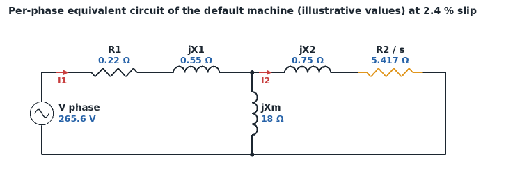
Solving the circuit at one slip
With the phase voltage as the reference (Vph = Vline / √3 for a wye, Vline for a delta):
Z2 = R2 / s + jX2 Zf = Zm ∥ Z2 Zin = R1 + jX1 + Zf
I1 = Vph / Zin power factor = cos(angle of Zin) I2 = I1 Zf / Z2
Zm is jXm, or jXm in parallel with a core-loss resistance Rc when one is entered. The symbol ∥ means "in parallel with": a ∥ b = a b / (a + b), in complex numbers.
Where the power goes
Pelec = 3 Vph I1 × power factor (input)
Pscl = 3 I1² R1 (stator copper loss) Pcore = 3 E1² / Rc (core loss, when Rc is entered)
Pag = 3 I2² R2 / s (air-gap power: what crosses to the rotor)
Prcl = s Pag (rotor copper loss) Pconv = (1 − s) Pag (converted to mechanical power)
Pout = Pconv − rotational losses efficiency = Pout / Pelec
The split of the air-gap power is the heart of the machine: the fraction s is lost as heat in the rotor and the fraction 1 − s turns the shaft. A motor running at 3 % slip can never be more than 97 % efficient.
Tind = Pag / ωsync Tshaft = Pout / ωm with ωsync = 4π f / poles and ωm = (1 − s) ωsync in rad/s
The Thévenin equivalent and the torque-speed curve
Everything to the left of the rotor branch (source, R1, X1, magnetizing branch) can be replaced by one voltage behind one impedance:
Vth = Vph Zm / (R1 + jX1 + Zm) Zth = Rth + jXth = Zm ∥ (R1 + jX1)
The tool uses these exact forms. Many course notes use the short forms Vth ≈ Vph Xm / (X1 + Xm), Rth ≈ R1 (Xm / (X1 + Xm))² and Xth ≈ X1, which hold when Xm is much larger than X1; answers then differ in the third figure.
Tind(s) = 3 Vth² (R2 / s) / (ωsync [(Rth + R2 / s)² + (Xth + X2)²])
starting torque: s = 1 pull-out slip: spo = R2 / √(Rth² + (Xth + X2)²)
pull-out torque: Tpo = 3 Vth² / (2 ωsync [Rth + √(Rth² + (Xth + X2)²)])
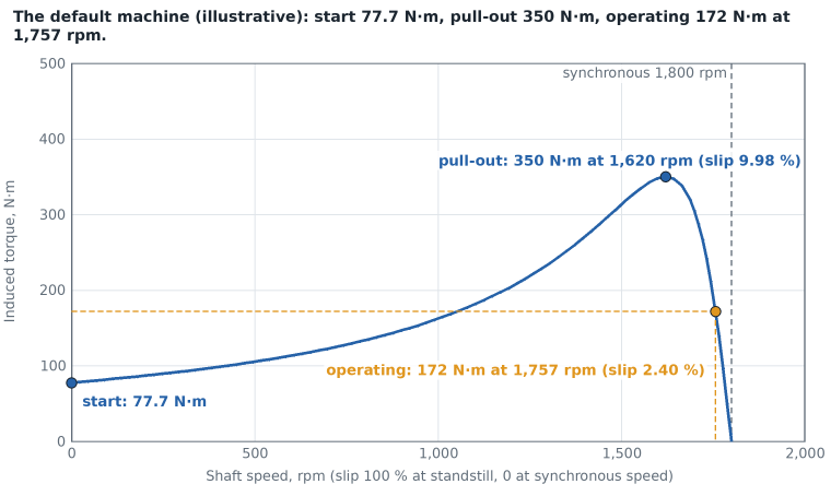
Three things follow from the formulas, and each is a "Try this" case:
- Rotor resistance moves the peak, not its height. R2 does not appear in Tpo, but spo is proportional to it. Adding resistance to a wound rotor slides the peak toward standstill; at R2 = √(Rth² + (Xth + X2)²) the peak is the starting torque.
- Torque goes with the square of the voltage. Vth is proportional to the line voltage, so at 80 % voltage every point of the curve drops to 64 %.
- The same R2 / s gives the same circuit. Ten times the rotor resistance at ten times the slip draws the same current and makes the same torque, with ten times the rotor copper loss.
Circuit parameters from the three tests
Line readings are first turned into phase values (wye: Vph = V / √3, Iph = I; delta: Vph = V, Iph = I / √3).
- DC test between two terminals: R1 = Vdc / (2 Idc) for a wye (two phases in series), R1 = 3 Vdc / (2 Idc) for a delta (one phase in parallel with the other two in series).
- No-load test at rated voltage and frequency: the rotor runs close to synchronous speed, R2 / s is very large and the rotor branch carries almost nothing, so X1 + Xm = Qnl / (3 Iph²) with Qnl = √((3 Vph Iph)² − Pnl²). The rotational losses are Pnl − 3 Iph² R1: friction, windage and core loss together.
- Blocked-rotor test at reduced voltage and often reduced frequency: |Zbr| = Vph / Iph, Rbr = Pbr / (3 Iph²), Xbr = √(|Zbr|² − Rbr²) at the test frequency.
Two ways of finishing are offered. The full circuit (the default) keeps the magnetizing branch at blocked rotor: the real and imaginary parts of R1 + jX1 + jXm (R2 + jX2) / (R2 + j(X2 + Xm)), with the reactances taken at the test frequency, are set equal to Rbr and Xbr and the two equations are solved numerically for X1 and R2. The classroom short form neglects the magnetizing branch at blocked rotor and takes the no-load impedance as all reactance: X1 + Xm ≈ Vph / Iph, R2 = Rbr − R1, X1 + X2 = Xbr scaled to rated frequency. The short form gives a somewhat smaller R2; the page lists both sets.
The tests fix only the sum of the two leakage reactances. How it is divided between stator and rotor is an assumption you choose: equal shares, or 40 % or 30 % to the stator for some cage designs (those shares are typed from memory of IEEE Std 112 and were not read for this page).
What it assumes
- A balanced three-phase supply of constant voltage and frequency, and a symmetrical machine in steady state.
- Constant circuit parameters at every speed: no saturation, no change of rotor resistance or leakage reactance with rotor frequency, no temperature rise.
- Rotational losses are one constant power, subtracted at the operating point only. Without a core-loss resistance the core loss is counted inside them. Stray-load loss is not modeled.
- The parameters are per phase of the winding as connected (wye or delta), with rotor values referred to the stator.
- Motoring only: slips from just above 0 to 100 %.
When it misleads
- Starting. Cage rotors are built with deep or double bars so that the rotor resistance is higher at standstill than at speed, and the iron saturates at starting current. A real cage motor therefore starts with more torque and a different current than the constant-parameter circuit gives. The curve is closest to a wound-rotor machine.
- Efficiency. It is only as good as the rotational and core losses entered; stray-load loss is left out, so the figure tends to be high.
- Low speeds with rotational losses. A constant loss power divided by a small speed is a large torque; the shaft torque is meaningful near the operating speed, not near standstill.
- Parameters from tests. The DC resistance is used as the AC resistance, the blocked-rotor values belong to the test frequency and current, and the split of the leakage reactance is assumed. Different textbooks reduce the same readings to slightly different circuits.
- Drives. A motor on a variable-frequency drive sees another voltage and frequency at every speed; one curve at fixed voltage and frequency does not describe it.
Common mistakes
- Using the line voltage in the per-phase circuit of a wye machine. The phase voltage is the line voltage divided by √3.
- Forgetting the factor 3 in the powers, or using it twice.
- Dividing the air-gap power by the shaft speed. Induced torque is Pag / ωsync (or Pconv / ωm, the same number); shaft torque is Pout / ωm.
- Putting rpm into a torque formula. ω is in radians per second: ω = 2π n / 60.
- Entering pole pairs for poles. A 1,800 rpm, 60 Hz machine has 4 poles.
- Using R2 instead of R2 / s in the circuit, or computing the rotor copper loss as 3 I2² R2 / s (that is the air-gap power; the loss is 3 I2² R2).
- Mixing the short-form Thévenin values with exact ones and wondering why the third figure differs from the book.
- Leaving the blocked-rotor reactance at the test frequency. Reactance is proportional to frequency: scale it to the rated frequency.
- Taking the DC reading across two terminals as R1. For a wye it is 2 R1; for a delta it is two thirds of the phase resistance.
Terms follow the DOE Fundamentals Handbook (slip, synchronous speed, breakdown torque). The page is a study aid: it does not rate, size or select a motor.