Tools › Building Systems › Plumbing › Gas Pipe Sizing › Method
Gas Pipe Sizing: Method
Gas Pipe Sizing: How It Works
What it does
The page takes a whole gas piping system as a tree of sections, each with its length and the appliance load at its end, and sizes every section with the flow equation printed in the fuel gas codes. It shows the load and flow each section carries, the smallest standard size whose equation capacity meets it, the pressure left at every outlet, and a comparison with the capacity you read from your adopted code table.
Sizes come from the flow equation, not from a code table. The fuel gas code adopted where you are, the authority having jurisdiction, and the appliance and pipe makers' instructions govern. Corrugated stainless steel tubing and other flexible tubing systems are sized from their maker's tables and are not covered. Gas piping work is for licensed installers. This page is not a design approval.
The idea
Gas leaves the meter (or a regulator) at a set pressure and loses a little pressure to friction in every section of pipe. The appliances need a minimum pressure at their inlets, so the piping is allowed only a small total drop, often half an inch of water column. Each section carries the gas for every appliance downstream of it. A longer pipe or a larger flow needs a larger diameter to stay within the same drop.
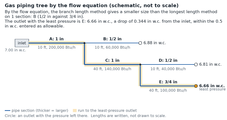
Step 1: the load and flow of each section
The load a section carries is the sum of the input ratings of every appliance at or beyond its end. The gas flow is that load divided by the heating value of the gas:
Q = H ÷ HV (Q in cubic feet per hour, H in Btu per hour, HV in Btu per cubic foot)
Natural gas is near 1,000 Btu per cubic foot and propane near 2,500, so the same appliance draws about two and a half times less volume of propane. Your gas supplier gives the local figure.
Step 2: the design length
| Method | Length used to size a section |
|---|---|
| Longest length | The length from the start of the piping to the most remote outlet of the whole system, for every section. |
| Branch length | Sections on the longest run use that longest length. Every other section uses the length from the start to the most remote outlet that it feeds. |
Both are the methods of section 402.4 of the International Fuel Gas Code. Using the whole run for every section spreads the allowable drop evenly along the pipe, so the drops of the sections on any path add up to no more than the allowable drop. The page computes the size by both methods and uses the one you select.
Step 3: the flow equation
For an inlet pressure under 1.5 lb/in² the codes print (Equation 4-1 of the International Fuel Gas Code):
D = Q0.381 ÷ [19.17 (ΔH ÷ (Cr L))0.206]
and for 1.5 lb/in² and above (Equation 4-2):
D = Q0.381 ÷ [18.93 ((P1² − P2²) Y ÷ (Cr L))0.206]
D is the inside diameter in inches, Q the flow in cubic feet per hour at 60 °F and 30 in of mercury, L the length in feet, ΔH the pressure drop in inches of water column, P1 and P2 the absolute pressures in lb/in² at the two ends (gauge pressure plus 14.7). The equations are for pipe and tube with smooth inside walls. The page solves them for the flow a standard size carries:
Qcap = [19.17 D (ΔH ÷ (Cr L))0.206]1/0.381
and picks the smallest standard size whose Qcap at the design length is at least the flow of the section. The factor Cr accounts for the viscosity, density and temperature of the gas (Appendix A of the same code):
Cr = 0.00354 S T (Z ÷ S)0.152
with S the specific gravity, T the absolute temperature (520 °R at 60 °F) and Z the viscosity in centipoise. It gives the code's values: 0.6094 for natural gas (S = 0.60, Z = 0.012) and 1.2462 for undiluted propane (S = 1.50, Z = 0.008). The factor Y is 0.9992 for natural gas and 0.9910 for propane.
The appendix of the code also prints the low-pressure equation solved for the flow with rounded exponents, Q = 2313 D2.623 (ΔH ÷ (Cr L))0.541. It gives about 0.6% less than Equation 4-1, and the code's capacity tables agree with it. This is one reason the equation capacity on this page can sit a little above a table value.
Step 4: the pressure at each outlet
With the sizes chosen (or the installed sizes you entered), the same equation solved for the drop gives the pressure lost in each section over its own length at its own flow:
ΔH = Cr L (Q0.381 ÷ (19.17 D))1/0.206
The pressure at an outlet is the inlet pressure less the drops of the sections on the way to it. At 1.5 lb/in² and above, the high-pressure equation is solved section by section for the absolute pressure at each end.
The Spitzglass option
An older low-pressure formula is offered in Advanced mode:
Q = 3550 √[ΔH D5 ÷ (S L (1 + 3.6/D + 0.03 D))]
It gives smaller capacities than the code equation for small pipe (about a quarter less for 1/2 in pipe) and nearly the same at 2 in. The constant 3550 was typed from memory in the form used by Crane Technical Paper 410 and checked against one worked value reported for a reference site; neither that paper nor the original 1912 paper was read.
Comparing with your adopted table
The fuel gas codes print capacity tables for set combinations of gas, pipe material, inlet pressure and pressure drop. Those tables, in the edition adopted where the work is done, govern. They are copyrighted and are not reproduced here. After a first run, look up the capacity of each section's size in the row for its design length (or the next longer row) and type it in the Table Capacity column. The page then states, for each section, whether the table value is at or above the demand and how far it is from the equation capacity. Small differences are expected: the tables are rounded, the next longer row is used, and some tables were computed with slightly different constants.
One table that is a U.S. government work can be used to try the comparison: the table of 24 CFR 3280.705(d) for manufactured homes (0.5 in w.c. drop). Its iron pipe values are within about 3.5% of Equation 4-1 at a specific gravity of 0.60, although the regulation's text names a specific gravity of 0.65.
What it assumes
- Every appliance runs at its full input at the same time.
- Smooth-wall pipe or tube with the standard inside diameters: steel pipe by ASME B36.10 (Schedule 40 or 80), copper tube by ASTM B88 (type K or L).
- Gas at 60 °F, with the specific gravity, heating value and viscosity entered.
- The lengths entered are the lengths that matter. Fittings count only through the percentage added in Advanced mode.
- The regime is set by the inlet pressure alone: the low-pressure equation under 1.5 lb/in², the high-pressure equation at and above it, with 14.7 lb/in² of atmosphere unless changed.
- No pressure is lost in the meter, regulators or valves, and none is gained or lost with height.
When it misleads
- When the adopted code table gives less capacity than the equation. The table governs.
- With corrugated stainless steel tubing or polyethylene pipe: neither is covered, and their capacities differ from smooth steel or copper of the same nominal size.
- With many fittings, valves or a long meter set: their losses are not in the lengths unless you add them.
- In tall buildings or at altitude: low-pressure gas gains or loses pressure with height (natural gas is lighter than air, propane heavier), and appliance ratings change with altitude.
- When an appliance needs more inlet pressure than the system's drop leaves. The page states the pressure left; it does not know the appliance's minimum.
- When the installed size of an existing section is not what was entered, or the pipe is rough or partly blocked.
- With a heating value or specific gravity that is not the supplier's.
Common mistakes
- Sizing a section for its own appliance only. A trunk carries everything downstream of it.
- Using each section's own length instead of the design length. The longest length method uses the length to the most remote outlet for every section.
- Adding an appliance and sizing only its new branch. The existing trunk now carries more, which is the first example on the page.
- Reading a natural gas table for propane, or a table for another pressure drop or inlet pressure.
- Mixing cubic feet per hour and Btu per hour. Divide the Btu per hour by the heating value to get cubic feet per hour.
- Using nominal size as the diameter. A 1 in Schedule 40 pipe has an inside diameter of 1.049 in; 1 in type L copper tube, 1.025 in.
- Reading the row for a shorter length than the run. Tables step in lengths; the next longer row applies.