Tools › Building Systems › Lighting and Electrical › Cable Pulling Tension › Method
Cable Pulling Tension: Method
Open the Cable Pulling Tension tool
Cable Pulling Tension: Straights Add, Bends Multiply
The tool takes a cable, a conduit and a run described as a list of straights and bends, and works out the tension in the cable at the end of every segment for a pull from either end, with the pressure the cable puts on the wall of every bend. It sets those figures beside the allowable tension and sidewall pressure typed in from the cable maker's data; it does not judge a pull.
The idea: where a bend sits matters more than how many there are
Dragging a cable along a straight conduit is dragging a weight along a floor: every foot adds the same friction, whatever the tension already is. A bend is different. The cable is held against the inside of the curve by its own tension, so the friction in a bend grows with the tension that arrives there. A straight adds to the tension; a bend multiplies it.
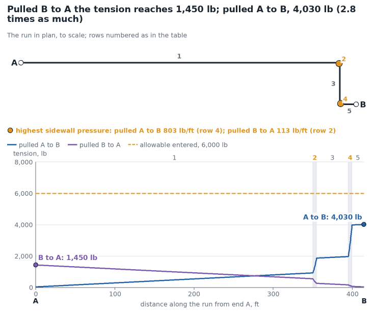
That is why the same run can need several times the pull in one direction as in the other, and why the tool always works both.
The equations
Symbols: T tension, Wt weight of all the cables per unit length, L length of a straight, θ its slope above the horizontal, μ coefficient of friction, Kw weight correction factor, φ angle of a bend in radians, R its radius, d cable diameter, D conduit inside diameter.
| Segment or quantity | Formula | Where it comes from |
|---|---|---|
| Straight, level | Tout = Tin + μ Kw Wt L | friction on the weight |
| Straight, rising at θ | Tout = Tin + Wt L (sin θ + μ Kw cos θ) | the weight along the slope is lifted; the weight across it gives friction |
| Straight, falling at θ | Tout = Tin − Wt L (sin θ − μ Kw cos θ), not below zero | the weight along the slope helps the pull |
| Horizontal bend, with the cable weight | Tout = Tin cosh(μ Kw φ) + √(Tin² + (Wt R)²) sinh(μ Kw φ) | wall force per length √((T/R)² + Wt²): tension sideways, weight downward |
| Horizontal bend, capstan form | Tout = Tin eμ Kw φ | the same with the weight left out (belt friction) |
| Vertical bend | Tout = (Tin − A sin αin − B cos αin) e−kφ + A sin αout + B cos αout | see below |
| Weight correction factor, three cables cradled | Kw = 1 + (4/3) (d / (D − d))² | statics of three circles side by side in a circle |
| Weight correction factor, three cables triangular | Kw = 1 / √(1 − (d / (D − d))²) | statics of two circles on the wall carrying a third |
| Sidewall pressure, one cable | P = T / R | the sideways load of a cable under tension on a curve |
| Sidewall pressure, three cradled | P = (3 Kw − 2) T / (3 R) | the share of the middle cable |
| Sidewall pressure, three triangular | P = Kw T / (2 R) | the share of each of the two cables on the wall |
| Jam ratio | J = k D / d, with k = 1.05 by default | three cables can wedge when the conduit is about three cable diameters wide |
Where the equations come from
One element of cable. Take a short length ds of cable sliding along the conduit. The tension rises along it by the part of its weight that has to be lifted plus the friction on whatever force n per unit length the wall puts on it: dT/ds = Wt sin α + μ Kw |n|, where α is the slope of the direction of pull. Every row of the table is this one equation with a different n.
- In a straight the wall carries the weight across the slope, n = Wt cos α, which is constant: the tension rises in a straight line.
- In a horizontal bend the tension pulls the cable against the inside of the curve with T/R per unit length, and the weight still presses down. The two are at right angles, so n = √((T/R)² + Wt²). Integrating gives the cosh and sinh form. When T is much larger than the weight of cable on one radius, Wt R, it becomes the capstan equation.
- In a vertical bend the sideways pull of the tension and the weight act in the same plane: n = Wt cos α − σ T/R, where σ is +1 for a bend that turns the run upward (the foot of a riser) and −1 for one that turns it downward (the top of a riser), and the slope changes through the bend, α = αin + σ φ. While n keeps one sign s (+1 with the cable on the floor of the conduit, −1 with the tension holding it against the roof) the equation is linear and its solution is the form in the table with k = μ Kw s σ, A = 2 σ s μ Kw Wt R / (1 + (μ Kw)²) and B = −σ Wt R (1 − (μ Kw)²) / (1 + (μ Kw)²). The tool follows n through the bend and changes s where n passes through zero. The four cases usually listed separately (pulling up or down, concave up or down) are this one equation entered at different slopes.
A cable cannot push. On a steep falling stretch the equations can give a tension below zero. The cable then runs by itself; the tool holds the tension at zero until it rises again and marks the stretch as slack.
Three cables. Three equal cables do not rest on the conduit the way one does. Lying cradled, the two outer cables lean on the middle one; in a triangle, two cables on the wall are wedged apart by the third. In both cases the wall forces add up to more than the weight. Writing the equilibrium of each cable (weight down, wall force toward the conduit center, contact forces along the line joining the cable centers) gives the two factors in the table, with c = d / (D − d) the sine of the angle that fixes the geometry. In a bend the same statics applies with the sideways load T/R in place of the weight, which gives the sidewall pressure on the most loaded cable. The factor is then applied to the friction in bends as well as in straights, as cable pulling practice does.
How the run is entered
- Rows go from end A to end B. Rising and falling are as walked from A to B; the tool mirrors them for the pull from B.
- A horizontal bend has to sit in a level stretch. Left and right change the drawing, not the tension.
- A vertical bend starts at the slope of the row before it and leaves at that slope plus or minus its angle. The straight after it has to continue at that slope: a 90 degree bend up from level is followed by a straight rising at 90 degrees.
- Straights that do not touch a vertical bend may change slope from one row to the next without a bend between them, as hand calculations do.
What it assumes
- A perfectly flexible cable: no force is needed to bend it into a curve or to straighten it afterwards.
- One coefficient of friction for the whole run, the same in straights and bends, independent of the pressure on the wall and of speed.
- The cables keep the chosen arrangement (cradled or triangular) all the way, and share the tension equally.
- The incoming tension at the feed end is the same whichever end the cable is fed from.
- Bends are circular arcs of the radius entered, and a horizontal bend lies in a level plane.
- The sidewall pressure uses the highest tension in the bend, which is nearly always the tension leaving it.
When it misleads
- The coefficient of friction is the weakest number. It varies with jacket, conduit, lubricant, temperature and wall pressure, and it sits in an exponent: in the figure's case, 0.45 in place of 0.35 raises the A to B tension by almost 90 percent.
- Stiff cables. Large or armored cables resist bending. The extra force to feed them through a tight bend is not in these equations.
- Low tension in a bend. The capstan form gives almost nothing where little tension arrives at a bend. The form with the cable weight does not, which is why the tool opens on it.
- A jam is not a tension. If three cables wedge across the conduit in a bend the pull stops; no equation here predicts the force. The jam ratio only says whether the diameters invite it.
- Slack stretches. Where the tool reports slack the cable is running ahead of the pull. The real tension there depends on how the reel is braked.
- Allowables are not in the tool. The ratios on the page are only as good as the allowable tension and sidewall pressure typed in, which depend on the conductor, the cable construction and how the cable is gripped.
Common mistakes
- Entering the bend angle in degrees in a hand calculation of eμKφ. The exponent needs radians: 90 degrees is 1.571.
- Working one direction only. The reverse pull is the same arithmetic in the opposite order and can differ severalfold.
- Adding the bends up: two 90 degree bends are not one 180 degree bend unless nothing lies between them, because the straight between them adds tension that the second bend multiplies.
- Using the weight of one cable when three are pulled, or leaving out the weight correction factor in the exponent of the bends.
- Taking the sidewall pressure from the tension entering the bend. It is the tension leaving that presses hardest.
- Entering the radius of a bend to the inside of the conduit, or in inches where the equations take feet.
- Treating a falling slope like a rising one. Downhill the weight term changes sign, and the tension can fall to zero.
Sources and checks
Every equation on this page is derived from the force balance above and was checked against an independent numerical integration of that balance (65 runs, both directions, agreement to better than one part in 100,000) and, for the three-cable factors, against a numerical solution of the equilibrium of the cables. The equations have the same form as those in cable makers' installation guides and in IEEE Std 1185, and the horizontal bend with cable weight and the vertical bend go back to Rifenburg (1953); those documents were not read for this page and are cited for the reader. The default jam band (2.8 to 3.2), the 1.05 ovality factor and the illustrative 500 lb/ft sidewall figure are numbers commonly printed in such guides, typed from memory: replace them with the figures of the guide that applies. No U.S. government manual with these equations was found.