Tools › Fluids and Heat Transfer › Fluid Statics › Hydrostatic Force and Buoyancy › Method
Hydrostatic Force and Buoyancy: Method
Open the Hydrostatic Force and Buoyancy tool
Method: Pressure Prism, Center of Pressure, Curved Surfaces, Manometers, Metacentric Height, Common Mistakes
What the tool does
It finds the force that a liquid at rest puts on a flat or curved surface and the point where that force acts, the pressure difference across a manometer, and whether a floating box or cylinder stays upright. Each answer comes with a drawing of your own case and the worked steps.
The idea: pressure grows with depth
In a liquid at rest the pressure at a depth h below the surface is p = γ h, where γ is the weight of the liquid per unit volume (62.4 lb/ft³ or 9.81 kN/m³ for fresh water). It pushes at right angles to any surface it touches. Drawn against a wall, the pressure forms a wedge, the pressure prism: zero at the waterline and largest at the bottom. The total force is the volume of that prism, and it acts through the centroid of the prism, which is why the force on a wall acts below mid-depth.
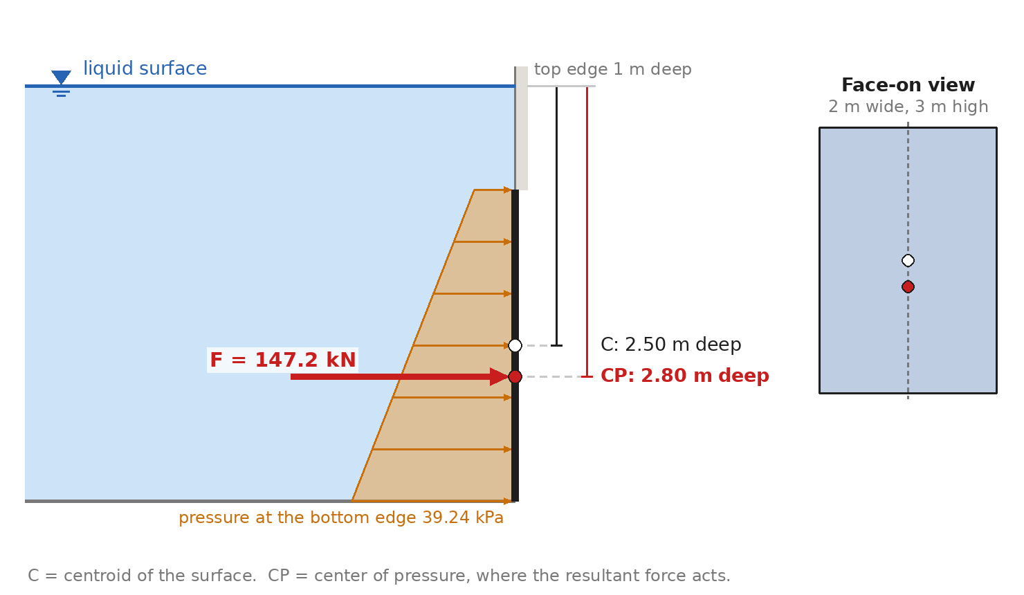
Flat surface
For a flat surface of area A whose centroid is at the depth hc, tilted at the angle θ from the horizontal:
- Force: F = γ hc A, at right angles to the surface. The pressure at the centroid times the area, whatever the shape or tilt.
- Center of pressure: it lies below the centroid by e = Ic sin θ / (hc A), measured along the surface, where Ic is the second moment of area of the shape about the horizontal axis through its centroid. Its depth is hcp = hc + e sin θ.
- With a gas pressure p0 on the liquid surface (a closed tank), replace hc by hc + p0 / γ in both formulas.
- Gate hinged along its top edge: moment about the hinge M = F scp, with scp the distance from the top edge to the center of pressure along the gate; the force at the bottom edge that holds it shut is M divided by the height of the gate. For a bottom hinge use the distance from the bottom edge.
| Shape | Area | Centroid below the top edge | Ic / A |
|---|---|---|---|
| Rectangle, width b, height h | b h | h / 2 | h² / 12 |
| Circle, diameter D | π D² / 4 | D / 2 | D² / 16 |
| Triangle, base b at the top, point down | b h / 2 | h / 3 | h² / 18 |
| Triangle, point up, base b at the bottom | b h / 2 | 2 h / 3 | h² / 18 |
| Semicircle, diameter D at the top | π D² / 8 | 2 D / (3 π) | 0.01747 D² |
| Semicircle, diameter D at the bottom | π D² / 8 | D / 2 − 2 D / (3 π) | 0.01747 D² |
The constant for the semicircle is (9 π² − 64) / (144 π²). For a rectangle that starts at the waterline the formulas reduce to the familiar F = γ b h² / 2 acting two-thirds of the way down.
Curved surface (circular arc)
Split the force into two parts that are each easy:
- Horizontal part: the force on the flat vertical projection of the wetted arc, FH = γ (H − hw / 2) hw w, where H is the liquid depth above the lowest point of the arc, hw the wetted height of the arc and w its width.
- Vertical part: the weight of the liquid that fills, or would fill, the space between the wetted arc and the level of the liquid surface, FV = γ V. It pushes down when the liquid is really above the surface and up when that space is on the dry side (this is buoyancy).
- Resultant: F = √(FH² + FV²). Because every bit of pressure on a circular arc points along a radius, the resultant passes through the center of the arc.
The tool evaluates both parts in closed form. With the center of the arc at the origin, a the height of the liquid surface above the center, and φ the angle of a point of the arc measured from the horizontal on the dry side, the wetted arc runs from φa to φ2 = 180° + θb and
Fx = ∓ γ w R [a sin φ − (R / 2) sin² φ], Fy = ∓ γ w R [−a cos φ − R (φ / 2 − sin 2φ / 4)], each bracket taken between φa and φ2,
with the upper sign when the arc bulges toward the liquid and the lower sign when the liquid is inside the curve. φa is the top end of the arc, 180° − θt, or the point where the liquid surface cuts the arc, 180° − sin⁻¹(a / R), whichever is lower. The projected-area form of FH above is printed as a check.
Manometer
Start at one end and walk along the tube to the other. Each time you go down through a fluid the pressure rises by γ h; each time you go up it falls by γ h, with h the vertical height of that leg and γ = SG × 9.80665 kN/m³ (62.43 lb/ft³). The widths of the tubes, the shape of the bends and the length of sloping parts do not matter, only heights. Two points at the same level in the same connected fluid have the same pressure, which is why a U-bend adds nothing.
Buoyancy and floating stability
Archimedes: a body in a liquid is pushed up by the weight of the liquid it displaces. A floating body sinks until that equals its own weight, W = γ V. For a box of length L and beam B, or an upright cylinder of diameter D, the sides are vertical, so the draft is T = W / (γ Awp) with Awp the waterline area.
- K is the bottom (keel). The center of buoyancy B is the centroid of the displaced liquid: KB = T / 2.
- The metacenter M is the point through which the buoyant force acts when the body heels a little: BM = I / V, with I the second moment of the waterline area about the axis of roll. Box: BM = B² / (12 T). Upright cylinder: BM = D² / (16 T).
- Metacentric height: GM = KB + BM − KG, with KG the height of the center of gravity. GM positive: the body comes back upright. GM negative: it rolls over.
A box rolls most easily about its long axis, so the beam (the shorter side) governs; the tool also prints GM for pitching, end to end.
What it assumes
- A liquid at rest with one constant density, and gravity of 9.80665 m/s².
- Liquid on one side of the surface only. Atmospheric pressure acts on both sides and cancels, so all pressures are gauge pressures.
- Flat shapes are symmetric left to right with a horizontal top or bottom edge, so the center of pressure lies on the centerline.
- The curved surface is part of a circular cylinder with a horizontal axis.
- The floating body has vertical sides, floats level, and its weight and cargo do not shift.
When it misleads
- A real dam or gate also carries uplift under its base, silt, ice, waves, flowing water over or under it and earthquake loads. A named dam in the examples is a plain vertical wall of the same height, not the real structure.
- A gate with liquid on both sides: run each side and subtract.
- Layered liquids (oil on water) on a wall: the pressure is no longer one straight line. Use the surface-pressure input for the lower layer, with p0 equal to the pressure at the interface.
- Metacentric height describes small angles of heel only. A positive GM does not show how far a vessel can heel before it capsizes, and liquid cargo that sloshes (free surface) reduces GM.
- Specific weights and specific gravities change with temperature and salinity. The built-in values are rounded.
Common mistakes
- Putting the force at the centroid. Only the size of the force uses the centroid; it acts lower, at the center of pressure.
- Using the two-thirds rule for a surface whose top edge is below the waterline. Two-thirds of the depth is right only for a rectangle that starts at the surface.
- Mixing slant distance and vertical depth on an inclined surface. Pressure depends on vertical depth; Ic and e are measured along the surface.
- Using the pressure at the bottom edge times the area. That doubles the force on a wall that starts at the surface.
- Forgetting the width. F = γ h² / 2 is a force per unit of width.
- Curved surface: using the arc length for the horizontal force (use the vertical projection), or forgetting that the vertical force can act upward.
- Manometer: adding instead of subtracting when the path goes up, or using the length of a sloping tube instead of its height.
- Mixing mass density and specific weight: γ = ρ g. In U.S. units 62.4 lbm/ft³ of water weighs 62.4 lbf/ft³.
- Stability: taking BM = I / V with I of the wrong axis, or measuring KG from the waterline instead of from the bottom.
- Adding atmospheric pressure to one side of an open tank wall.
Checks behind this page
The library is tested against the printed examples of U.S. government documents: the pressures at 10, 20 and 30 ft and the force on a tank bottom in the Department of Energy fundamentals handbook; the flood force of 124.8 lb/ft and the buoyant forces in the Federal Emergency Management Agency manual; the buoyancy examples of the U.S. Naval Academy ship performance notes; and the Bureau of Reclamation's figure for the water pressure at the base of Hoover Dam. Every flat and curved surface is also checked against a numerical integration of the pressure, and the metacentric height against a box tilted by half a degree. No printed government example was found for the curved gate, the manometer chain or the metacentric height of a box, so those rest on the numerical checks. The specific gravities of mercury (13.6) and seawater (1.025) are rounded handbook values entered from memory.