Tools › Structures › Statics › Truss by Joints and Sections › Method
Truss by Joints and Sections: Method
Open the Truss by Joints and Sections tool
Method of Joints, Method of Sections, Zero-Force Rules and Common Mistakes
What the tool does
You describe a plane truss: its joints, the members between them, the supports and the loads at the joints. The tool finds the force in every member the way it is done by hand (reactions first, then zero-force members, then one joint at a time, then an optional section cut), writes each equation with your numbers, and draws the truss to scale with tension and compression in different colors.
The idea
A truss is made of straight bars pinned together at their ends and loaded only at the joints. Such a bar can only be pulled or pushed along its own length, so each member carries one number: a tension (the bar is being stretched) or a compression (it is being squeezed). Because every joint is at rest, the forces on it must cancel. Cut a joint out of the truss, draw the forces on it, and two equations hold:
ΣFx = 0 ΣFy = 0
Two equations find two unknowns. So the work is a walk through the truss: start at a joint with no more than two unknown member forces, solve it, and move to a neighbor that now has no more than two.
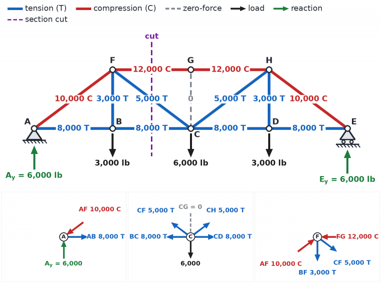
Above: the solved truss (the tool's first Try this case, forces in pounds). Below: joints A, C and F cut free. An arrow pointing away from a joint is a member in tension pulling on it; an arrow pushing into the joint is a member in compression.
Sign convention
x is positive to the right, y upward, moments counterclockwise. Every unknown member force is drawn pulling away from the joint, that is, as tension. A positive answer is then tension (T) and a negative answer is compression (C); there is no need to guess the direction in advance. Unknown reactions are assumed to act to the right or upward, and a negative answer means the opposite.
The part of a member force along x is the force times (Δx / L), and along y the force times (Δy / L), where Δx and Δy run from the joint to the member's other end and L is its length. These two ratios are the direction cosines; the tool prints them in brackets after each force. A member that rises 3 for every 4 it runs has length 5 and cosines (0.8, 0.6).
Step 1: is the truss statically determinate?
Count the members m, the reaction components r (a pin gives 2, a roller 1) and the joints j. Each joint gives two equations, so there are 2j equations for m + r unknowns.
| Count | Meaning | What the tool does |
|---|---|---|
| m + r = 2j | statically determinate, if the arrangement is also stable | solves it by joints and sections |
| m + r > 2j | statically indeterminate: more unknowns than equations | stops and points to the matrix tool, Truss and Frame Analysis |
| m + r < 2j | a mechanism: it can move without any bar changing length | stops and says how many members or reactions are missing |
The count is necessary but not sufficient. A truss can have the right count and still be unstable: one panel with two diagonals and its neighbor with none, or three reactions that are parallel or all point at one spot. The tool tests this by checking whether the 2j equations have one solution, and says so when they do not.
Step 2: reactions from the whole truss
Treat the entire truss as one rigid body. The member forces are internal: they come in equal and opposite pairs and drop out. What is left are the loads and the three reaction components, and three equations: ΣFx = 0, ΣFy = 0 and ΣM = 0 about any point. Taking moments about the pin removes both of its components and gives the roller reaction in one line. The Equilibrium and Free-Body Diagram tool treats this step at length.
Step 3: zero-force members
Some members carry nothing under a given loading and can be found by inspection, which shortens the rest.
Rule 1. If only two members meet at a joint, they are not in one straight line, and the joint has no load and no support, both members are zero-force. (Neither can balance the other.)
Rule 2. If three members meet at a joint, two of them are in one straight line, and the joint has no load and no support, the third member is zero-force. (Nothing else at the joint has a part across that line.)
The rules can be applied again after a member has been found to be zero: with that member set aside, a joint that had four members may now look like a rule-2 joint. The tool lists each zero-force member with the rule and the joint that shows it. A zero-force member is still needed: it keeps the truss stable, shortens the unbraced length of a compression member, and carries force when the load moves.
Step 4: method of joints
For each joint in turn:
ΣFx = 0: the sum over the members at the joint of F (Δx / L), plus the x parts of any load and reaction there, is zero.
ΣFy = 0: the same with (Δy / L) and the y parts.
The tool always picks a joint with one or two unknowns. If one of the two equations holds a single unknown it is solved first; otherwise the two are solved together. When a joint has only one unknown left, the spare equation is shown as a check. At the end every member is known and the last joints have nothing left to find: their equations must come out to zero, which checks the whole calculation.
In a compound or complex truss the walk can stop: every remaining joint has three or more unknowns. By hand the way forward is a section. The tool says where this happens and takes the remaining forces from the solution of all the joint equations at once.
Step 5: method of sections
To find the force in a few members without working through the joints, pass an imaginary cut through the truss that divides it into two parts and crosses no more than three members whose forces are unknown. Keep either part. It is a rigid body in equilibrium under its own loads and reactions and the forces in the cut members, so three equations are available. The skill is to choose each equation so that it holds one unknown:
To find one cut member, take moments about the point where the lines of the other two cross. Both pass through that point and have no moment about it.
If the other two are parallel (the top and bottom chords of a bridge truss), they never cross. Sum the forces at right angles to them instead: only the third member, the diagonal, has a part in that direction.
The moment of a force about a point P is MP = dx Fy − dy Fx, with dx and dy measured from P to any point on the force's line. The crossing point need not be a joint, or even lie on the truss. The tool keeps the part with fewer forces on it; for a cantilever truss that is the free end, so the reactions are never needed.
What it assumes
All members are straight, weightless and joined by frictionless pins; all loads and reactions act at joints; everything lies in one plane; the truss does not change shape noticeably under load. Real trusses have bolted, welded or gusset-plate joints and members with weight, yet the pin-jointed model gives the axial forces well when the member center lines meet at a point at each joint and the loads are brought to the joints.
When it misleads
A load applied between joints bends the member it sits on; the truss model does not see that. Share such a load between the two end joints for the axial forces, and check the member in bending separately.
The forces say nothing about strength. A slender member in compression buckles at a load far below the one that would crush it, so the largest compression is often more critical than the largest tension.
A statically indeterminate truss (a second diagonal in a panel, a truss on two pins) shares load according to the stiffness of its members. Statics alone cannot solve it and this tool does not try.
The tool was checked against an independent solution of the joint equations and against the site's matrix tool on several hundred trusses, not against a published worked example. Treat it as a teaching aid and a check on hand work.
Common mistakes
- Mixing up the sense of a member force. A member in tension pulls on the joints at both of its ends; one in compression pushes on both. On a joint's free body, tension points away from the joint. Carrying a force from one joint to the next, keep the same value and sign; do not flip it.
- Starting at a joint with three unknowns. Two equations cannot find three forces. Find the reactions first and start at a support, or at a free corner with two members.
- Forgetting the reaction (or the load) on a joint's free body. At a support joint the reaction is one of the forces; leave it out and every force after it is wrong.
- Swapping sine and cosine. Take the parts from the geometry, Δx / L and Δy / L, and the question of which angle was meant never comes up.
- Calling a member zero-force when the joint has a load or a support. Both rules need an unloaded, unsupported joint. And rule 2 names the member that is not in line with the other two.
- A cut that does not divide the truss. The section must leave two separate pieces. If a member still joins them, it has been missed and its force belongs in the equations.
- Putting forces from both sides of the cut in one equation. Use only what acts on the part you kept: its loads, its reactions and the cut members.
- Taking moments about a point on the member you want. Its force has no moment there and drops out. Take moments about the crossing of the other two.
- Trusting m + r = 2j alone. The count can be right for a truss that folds. Every panel should be a triangle.
- Dropping the sign of a compression force when it is used at the next joint. Enter it as a negative number and let the algebra work.