Tools › Structures › Statics › Equilibrium and Free-Body Diagram › Method
Equilibrium and Free-Body Diagram: Method
Open the Equilibrium and Free-Body Diagram tool
Method, Support Types, Sign Convention and Common Mistakes
What the tool does
You describe one rigid body in a plane: a few points, the supports that hold it and the loads on it. The tool draws its free-body diagram to scale, writes the three equilibrium equations with your numbers, solves the support reactions in the order you would by hand, and checks the answer about a second point.
The idea
A body at rest stays at rest only if the forces on it cancel and their turning effects cancel. To use that, the body is first cut loose from everything that touches it, and each support is replaced by the force it can exert. That drawing is the free-body diagram. Below, the same beam is shown on its supports and then as a free body: the pin at A becomes two unknown components, the roller at D becomes one, and the spread load becomes a single force at the middle of its length.
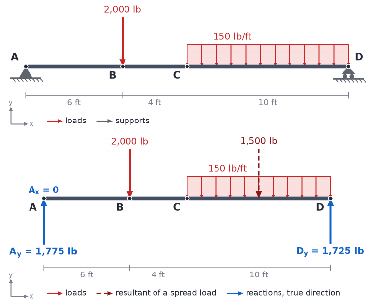
Then three equations hold for the free body:
ΣFx = 0 ΣFy = 0 ΣMP = 0 (about any point P)
Three equations find three unknowns. That single count decides most of what follows.
Sign convention and angles
x is positive to the right, y upward, and moments are positive counterclockwise. Every angle on the form is measured counterclockwise from the +x axis and gives the direction in which a force points: 0° to the right, 90° up, 180° to the left, 270° straight down. Every unknown reaction is drawn in an assumed positive direction (to the right, up, counterclockwise; a cable or link pulling on the body). A negative answer is not an error: it means the force acts opposite to the assumed direction. The figure always draws reactions the way they really act.
Supports and the unknowns that replace them
| Support | What it prevents | Unknowns |
|---|---|---|
| Pin (hinge) | movement in x and in y; the body can turn | 2: Ax, Ay |
| Roller on a floor, on a wall, or at an angle | movement into the surface only | 1: a force perpendicular to the surface |
| Fixed (built in) | movement in x and in y, and turning | 3: Ax, Ay, MA |
| Cable | movement away along its line; it can only pull | 1: tension T along the cable |
| Link (a straight bar pinned at both ends, loaded only at its ends) | movement along its line, either way | 1: a force along the link |
A cable or link "to a point" takes its direction from the geometry: from the point on the body toward the anchor named in the To column.
Spread loads
A load spread along a line acts on a rigid body like one force equal to the area of its load diagram, placed at the centroid of that area. With w the load per unit length and L the length it covers:
Uniform load: R = w L, at L / 2.
Triangular load (zero at one end, w at the other): R = ½ w L, at L / 3 from the larger end.
A load that varies linearly between two non-zero values is split into a rectangle and a triangle; one that changes sign along its length is split into two triangles. This replacement is right for the reactions of the whole body. It is not right for internal forces: the shear and bending moment inside a beam depend on how the load is spread.
Moments, and where to take them
The moment about P of a force with components Fx, Fy acting at a point a distance dx to the right of P and dy above it is
MP = dx Fy − dy Fx
which is the same as force times perpendicular distance, with the sign set by the sense of turning. A couple adds its own value whatever the point.
Any point gives a valid equation, but a force has no moment about a point on its own line of action. Taking moments about the point where two unknowns cross removes both from the equation and leaves the third alone. The tool looks at every support point and every crossing of two reaction lines, picks the one that removes the most unknowns and says which. You can also name the point yourself to follow a worked solution in a book.
The reactions are then put back and the moments are summed about a second point. Because a body in equilibrium has no net moment about any point, this is an independent check of the arithmetic.
Counting unknowns: four possible outcomes
Statically determinate. Three unknowns, and the reaction lines are neither all parallel nor all through one point. The three equations give one answer.
Statically indeterminate. More than three unknowns, for example a beam on two pins or a fixed beam with an added roller. The body is held, but equilibrium alone cannot say how the supports share the load; that depends on how the body deforms. The number of extra unknowns is the degree of indeterminacy.
Partially constrained. Fewer than three unknowns. The body can move in some way that no support resists. It may still be in equilibrium under a particular loading (a beam on two rollers under vertical loads); the tool then solves it and says the answer holds for that loading only. Otherwise it reports which load component or moment is left unbalanced.
Improperly constrained. Enough unknowns, badly arranged. If all the reaction forces are parallel, nothing resists a push across them. If all their lines of action meet at one point, nothing resists turning about that point. The equations then have no solution, and the tool gives the reason and what to change.
Friction check
A pin can stand for a rough contact, such as the foot of a ladder: it supplies whatever normal force N and friction force F equilibrium demands. The surface can supply at most μs N. The tool resolves the pin reaction into N (normal to the chosen surface) and F (along it) and reports the coefficient needed, μ = F / N, against the coefficient entered. If the needed value is larger, the contact slips and the body is not in equilibrium as drawn.
What it assumes
One rigid body, in one plane, at rest (or moving at constant velocity). Supports are ideal: pins and rollers have no friction, cables and links have no weight, a fixed support does not rotate. The weight of the body is included only if you enter it as a load at its center of gravity. Units follow the unit selectors of the tables; moments are reported in the force unit times the length unit.
When it misleads
A roller on a surface can only push, and a cable can only pull. The equations do not know this. The tool flags a cable that would have to push, but it cannot tell which side of a roller the surface is on: if a roller reaction points from the body toward its surface, the body would lift off and the answer does not apply. The friction check treats one contact; problems in which slipping is about to start at two contacts at once, or in which a body may tip before it slips, need those conditions written as extra equations. Nothing here checks strength or deflection.
Common mistakes
- Leaving a force off the diagram. The weight of the body and every reaction component belong on it; a pin always brings two components, a fixed support two and a moment.
- Drawing forces that act on something else. A free-body diagram shows forces on the body only, not the forces the body exerts on its supports.
- Putting the resultant of a triangular load at mid-length. It acts at one third of the length from the larger end.
- Using the wrong distance in a moment. The arm is the perpendicular distance from the point to the line of action, not the distance to the point where the force is applied. Splitting a slanted force into x and y components avoids the error.
- Dropping a sign. Choose counterclockwise as positive once and keep to it for every term.
- Forgetting a couple, or multiplying it by a distance. A couple enters the moment equation as it is, about any point, and does not appear in the force equations.
- Reading a negative answer as wrong. It only reverses the assumed direction. Do not change the sign halfway through the solution.
- Writing a fourth equation. A second or third moment equation is a check, or a replacement for a force equation, never an extra independent equation. A plane body gives three.
- Letting a cable push or a roller pull. If the solution asks for it, the body is not held the way it was drawn.
How it was checked
The solver is compared with an independent numerical solution of 240 random bodies using every support and load type, with the printed answers of three worked examples in OpenStax University Physics (a torque balance, a ladder on a smooth wall and a door on two hinges), and with the closed forms for simple beams and cantilevers. The six cases of the Try this bar are original examples, not taken from a book.