Tools › Structures › Joints › MIL-HDBK-5J Fastener Allowables › Method
MIL-HDBK-5J Fastener Allowables: Method
Open the MIL-HDBK-5J Fastener Allowables tool
Method: How the Tables Are Read, Which Tables Are In, What It Assumes, Common Mistakes
What the tool does
It looks up the static strength of one fastener in one sheet from the joint tables of MIL-HDBK-5J, Chapter 8: you choose the fastener and sheet combination, a diameter and a sheet thickness, and it returns the ultimate and yield strength printed in that cell, the fastener shear strength that caps the column, the table's footnotes and its page. It does not calculate a joint strength; it reads one that was established by test.
The idea: a joint allowable is a tested number, not a formula
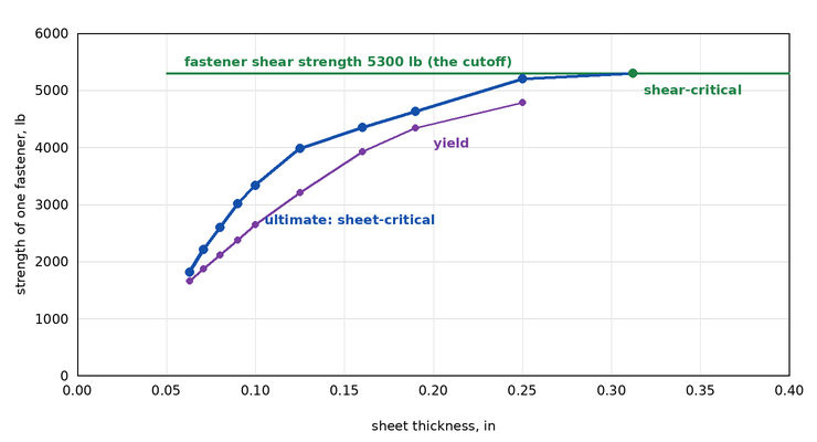
A fastener in a sheet can fail in two places. In thin sheet the sheet gives way first: the hole elongates in bearing, or a countersunk head rolls and pulls through. In thick sheet the fastener itself shears. For a plain hole and a protruding head both strengths can be computed. For a flush head they cannot, because the countersink removes part of the bearing surface and the head tilts under load, so the handbook tabulates values from tests of that fastener in that sheet. Each column of a table therefore rises with sheet thickness and then stops at the shear strength of the fastener.
The equations the chapter gives
The shear strength of the fastener, the last row of each ultimate block, is a shear stress level times an area:
Ps = Fsu π D² / 4
D is the nominal hole diameter for a driven solid rivet (Table 8.1.2(a)) and the nominal shank diameter for a pin or bolt; the footnote of each table names its basis, and for some blind fasteners the printed value is a specification value a few percent away from this product. The tool shows the product and the printed value side by side and uses the printed one.
For threaded fasteners by themselves (Tables 8.1.5(a), (b1) and (b2)) the handbook states that every value is a stress level times an area:
Ps = Fsu Ashank Pt = Ftu Aminor
with the shank area from the basic shank diameter and the tension area from the minor diameter of the thread. The joint strengths themselves have no equation: they are the tabulated test values.
Two ratios are printed because the handbook's text refers to them: sheet thickness over diameter t / D (bearing values for plain holes apply at t / D of 0.18 and above; countersunk joints below 0.25 need increased attention to detail design) and, for a flush head, head height over sheet thickness (at 1 the countersink reaches through the sheet: a knife edge).
How a cell is chosen
- Table and sheet group. Each list entry is one table and one of its sheet-material groups, named as the handbook names them.
- Diameter. The entered diameter must be within 0.005 in of a column's size (3/16 = 0.1875 in) or of the nominal diameter printed under it (0.190 in). For the threaded-fastener tables, which list sizes as close as 0.188 and 0.190 in, the match is within 0.0008 in.
- Thickness. A thickness within 0.001 in of a tabulated gage is that gage. Between two gages the tool takes the thinner one and says so. Outside the rows printed for that diameter it gives no result.
No interpolation. Chapter 8 and Section 9.7 of the handbook contain no statement that allows interpolation between sheet gages (the text was searched for it), and the footnotes of several tables forbid extrapolation ("In no case shall allowables be obtained by extrapolation for gages other than those shown", Table 8.1.2.2(c)). Many organizations do interpolate between gages under their own design manuals; that is their rule, not the handbook's, and this tool does not apply it.
Where the numbers come from
No value was typed. A script reads the text layer of the handbook PDF page by page, places every number in its column by the ruling lines drawn on the page, and finds the knife-edge staircase from the short lines drawn inside the ultimate block. Each table then had to pass a blind reading: seeded rows, the shear strength row, the head height row and the position of the knife-edge line were read from an image of the page without sight of the parsed values, and compared. A table that could not be parsed completely, or whose footnotes could not be read in full, was left out.
In the tool (115 joint tables, 7,599 printed strength values, and 4 fastener tables with 492 values):
- Solid rivets: 8.1.2.1(c) and 8.1.2.2(a) to (t).
- Blind fasteners: 8.1.3.1.1(a) to (e); 8.1.3.1.2(a) to (t); 8.1.3.2.1(a) to (g); 8.1.3.2.2(a) to (m), (p) to (s), (u), (w) to (aa); 8.1.3.2.3(a), (b1), (b2), (d) to (h).
- Swaged collar fasteners: 8.1.4.1(a), (b) and 8.1.4.2(a) to (j).
- Threaded fasteners: 8.1.5.2(a1) to (o).
- Fastener alone: 8.1.2(b) driven solid rivets in single shear (with the hole diameters of 8.1.2(a)), 8.1.5(a) threaded fasteners in single shear, 8.1.5(b1) and (b2) threaded fasteners in tension.
Not in the tool: Tables 8.1.3.2.2(n), (o), (t1), (t2), (v) and 8.1.3.2.3(c) (the parser could not place every cell); 8.1.6.2(a) and (b), sleeve bolts (a footnote is a typeset formula that could not be read in full); 8.1.4, lockbolt shear and tension; 8.1.2.1(a) and 8.1.5.1, unit bearing strengths; 8.1.2.1(b), shear correction factors for protruding-head rivets; 8.1.1.1, shear stress levels; and all of Section 8.2 (welded, brazed and bonded joints).
What it assumes
- One fastener in single shear, in the sheet material and condition of the table, installed with the hole size, fit and grip the footnotes state, by the manufacturer the footnote names.
- An edge distance of two diameters: "the allowables are applicable only to joints having 2D edge distance" (Section 8.1.1.3).
- For a machine-countersunk joint, the thickness entered is that of the countersunk sheet. If the other sheet is thinner, its bearing strength must be computed and the lower value used (Sections 8.1.3, 8.1.4.2 and 8.1.5.2).
- Room temperature unless the table states another, static load, no fatigue.
- With several fasteners, each carries an equal share. That is the tool's assumption for the optional joint total, not a handbook statement.
When it misleads
- The document is from 2003. MIL-HDBK-5J was superseded by MMPDS, which has added, changed and removed fastener tables. A value used for design must come from the edition your program requires.
- A different part number is a different joint. The values belong to the fastener and collar or nut named in the table and to the data source in its footnote. A similar fastener from another maker is not covered.
- Yield can govern. In many flush tables the yield value is less than two thirds of the ultimate; the handbook marks some such cells with a footnote. Check limit load against yield as well as ultimate load against ultimate.
- Knife edge. Values above the line drawn in a table are for a countersink through the full sheet. The handbook calls their use undesirable and requires the procuring agency's approval for military aircraft.
- The handbook's own irregularities are kept. A few columns do not rise steadily with thickness (for example 4,924 lb then 4,901 lb in Table 8.1.5.2(f)); the tool prints what the page prints.
- SI values are conversions. The handbook prints pounds and inches. Newtons and millimeters are those numbers converted, and a metric sheet gage is not the inch gage the test used.
Common mistakes
- Entering the table with the total stack thickness, or with the thicker sheet. Use the countersunk sheet for a flush head, and read the footnote for dimpled sheet.
- Using the fastener shear strength as the joint strength in thin sheet. In the figure above the 1/4 in pin carries 1,813 lb in 0.063 in sheet, about a third of its 5,300 lb shear strength.
- Reading the column of the right diameter under the wrong sheet group. One page often holds several sheet materials with the same diameters repeated.
- Dropping the footnote letter. A raised letter on a value is part of the value: knife edge, yield below two thirds of ultimate, a different hole size.
- Interpolating between gages, or reading past the last printed row, without a rule that allows it.
- Forgetting the edge distance. Below two diameters the tables do not apply.
- Comparing limit load with the ultimate value, or forgetting that the yield value has its own check.
- Confusing the nominal size with the nominal hole or shank diameter: a 3/16 rivet fills a 0.191 in hole, a "5/32" Hi-Lok has a 0.164 in shank.
Related tools
Fastened Joint Strength takes a fastener allowable as an input and adds bearing, shear-out and net-section checks. MIL-HDBK-5J Allowables gives the sheet's bearing strengths Fbru and Fbry.