Tools › Structures › Composites › Composite Bearing-Bypass › Method
Composite Bearing-Bypass: Method
Open the Composite Bearing-Bypass tool
Composite Bearing-Bypass Strength: the Joint Element, the Eight Points of the Hole Boundary and the Effective Stress Concentration Factors
What the method does
A fastener in a composite joint loads its hole in bearing while the rest of the load in the laminate passes around the hole as bypass. Both raise the stress at the hole boundary, in different places, and a laminate does not fail when the elastic peak stress reaches its strength: damage in a small zone at the hole relieves the peak, and it does so over a length that belongs to the material, not to the hole. Eisenmann's model (NASA TM X-3377) puts that length into a fracture-mechanics form. At eight points of the hole boundary it imagines a short radial crack of the characteristic length a, computes its stress intensity under the applied loads, and compares it with the fracture toughness measured for that direction. Written as stresses, the comparison is between an effective tangential stress at the point and the unnotched strength of the laminate along the tangent there.
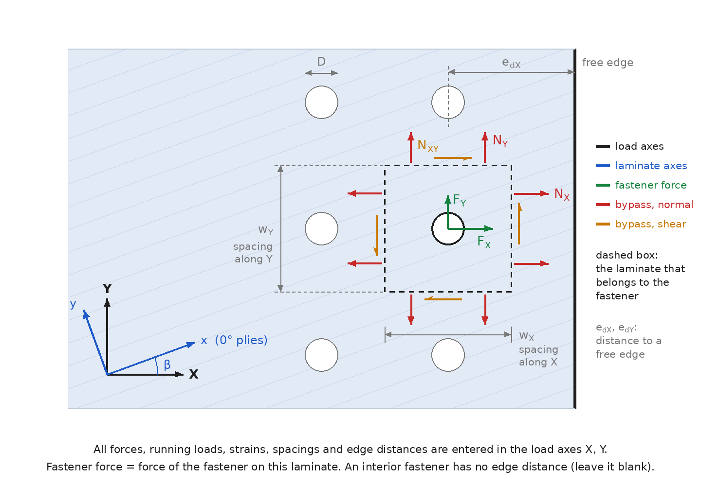
The joint element and its axes
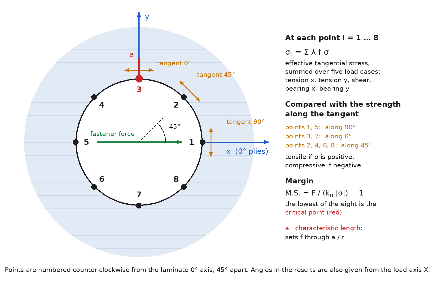
Each fastener is taken with a rectangle of laminate around it. The laminate axes are x along the 0° plies and y across them. The element has the hole diameter D, the distance E from the hole center to the element boundary along x, and the width W along y. Its loads are the bypass stresses σtx, σty and τxy, uniform on its boundary, and the bearing stresses σbx and σby, each a component of the fastener force divided by D t. The eight points are numbered counter-clockwise: point 1 on the +x axis, point 2 at 45°, point 3 on the +y axis, and so on to point 8 at 315°.
The page takes all loads in load axes X, Y, which may be turned from the laminate by the offset angle β (from X to the laminate 0° direction). The fastener force is turned as a vector and the bypass running loads as a tensor: Nx = NX cos² β + NY sin² β + 2 NXY sin β cos β, Ny = NX sin² β + NY cos² β − 2 NXY sin β cos β, Nxy = (NY − NX) sin β cos β + NXY (cos² β − sin² β). This is how the paper's own off-axis coupons were loaded.
Shear is positive in the usual sense: it stretches the +45° diagonal, which puts tension on the hole boundary at points 4 and 8 and compression at points 2 and 6. The paper's Figure 2 draws the opposite sense, which is why its Table III lists points 2 and 6 as the positive ones; the physics is the same.
The effective stress (Eq. 7)
At point i the effective tangential stress is the sum over the five load cases
σi = λtx ftx σtx + λty fty σty + λxy fxy τxy + λbx fbx σbx + λby fby σby
and the point fails when σi reaches the unnotched tensile strength of the laminate along the tangent at that point, or the compressive strength when σi is negative. The tangent is along 90° at points 1 and 5, along 0° at points 3 and 7 and along 45° at the other four. The margin of safety is strength / (ku |σi|) − 1 at the worst point, with ku the factor of safety when limit loads are entered and 1 when ultimate loads are entered.
The factor f(a/r)
The factor f is the stress intensity of the radial crack divided by √(π a), so it acts as an effective stress concentration factor. The paper gives it in two steps.
Isotropic plate (Table II). Curve fits f̂(a/r) of boundary-integral results, r the hole radius. With u = a/r:
- Tension across the crack (tension in x at points 3, 7; in y at 1, 5): f̂ = 1 / (0.2949 + 0.7051 u / (1 + u1.2)0.8333), not below 1.
- Tension at the 45° points: f̂ = 0.73 − 0.14 u + 0.40 exp(−3.689 u), not below 0.5.
- Tension parallel to the crack (tension in x at points 1, 5; in y at 3, 7): f̂ = −0.16 + 0.095 u − 0.97 exp(−4.169 u), not above 0.
- Shear at the 45° points: f̂ = 1.682 [1 / (0.2949 + 0.7051 u / (1 + u1.2)0.8333) − 1] + 0.5, not below 0.5.
- Bearing at the bearing point: f̂ = 0.452 − 0.085 u1/2 − 0.171 u1/3, not below 0.
- Bearing at the 45° points beside it: f̂ = 0.406 − 0.116 u + 0.447 exp(−4.344 u), not below 0.
- Bearing at the net section: f̂ = 0.370 − 0.070 u + 0.545 exp(−4.914 u), not below 0.
Bearing does not act at the three points behind the fastener, and shear does not act at points 1, 3, 5 and 7.
Orthotropic laminate (Eq. 8, Tables III and IV). The elastic stress concentration factors Kt of the hole in the orthotropic plate follow from the laminate constants (Lekhnitskii): −√(Ey/Ex) and 1 + √(2(√(Ex/Ey) − νxy) + Ex/Gxy) for tension in x at points 1, 5 and 3, 7, the same with x and y exchanged for tension in y, and combinations of these with the 45° modulus Eθ = 4 / ((1 − 2νxy)/Ex + 1/Ey + 1/Gxy) at the 45° points and for shear. The bearing values are the paper's fits in terms of the tension values. Then
f = { B1 [1 − (a/r) B2] [f̂ − B3] + B3 } B4, B2 = (1 − 1/B1) / (a/r)c
for 0 ≤ a/r ≤ (a/r)c, and f = f̂ B4 beyond. B1 is the ratio of the laminate's Kt to the isotropic one, so f(0) = 1.13 Kt B4: a vanishing crack feels the elastic peak. The correction fades linearly and is gone at (a/r)c, between 0.25 and 0.70 by load case. B4 is an empirical constant the author fitted to tests of single load cases (0.7 to 1.2).
The finite-width factor λ
The factors above are for an infinite plate. Tables VII to XIX of the paper give λ for each load case and point group against E/D (2 to 5, or 2 to 4), W/D (2 to 10) and the Kt of the load case. They were generated with boron/epoxy laminates of 0° and ±45° plies; the paper states they are approximately right for other materials when entered by Kt. The page interpolates linearly in D/E, D/W (in which the tables are evenly spaced) and Kt. Outside a table the edge value is held and the fastener is flagged; nothing is extrapolated.
What E and W stand for. The paper's element has two dimensions, E along the laminate x axis (from the hole center to the boundary on one side) and W along y, and each plays a different part by load direction. For tension or bearing along x, W is the width of laminate across the load, the net section, and E is the distance to whatever lies ahead of the fastener, an edge distance. For tension or bearing along y the parts change over: E is the half-width across the load and W is twice the distance to the edge ahead. The page therefore sets the element by load case from the fastener spacings and the edge distances:
- Tension in x, bearing in x: W = spacing along y; E = edge distance along x.
- Tension in y, bearing in y: E = half the spacing along x; W = twice the edge distance along y.
- Shear: E = half the spacing along x, W = spacing along y.
An interior fastener has no free edge near it, so its edge distances are left blank and the largest tabulated value is used along the load (E/D = 5, or W/D = 10): no edge effect. Its neighbors set the spacing, which is the width across the load. When β is not 0° or 90° the rectangle is not square to the laminate axes as the tables assume; the spacings and edge distances entered along X and Y are assigned to the nearer laminate axis.
The tables take the laminate to run on beyond the hole on the side away from E. For an interior fastener loaded along y there is a neighbor at one spacing on both sides, which the tables cannot show.
What an edge distance does here, and what it does not. It only selects λ. A nearer edge raises the stress at the net-section and 45° points and lowers it a little at the bearing point. The page makes no net-tension check on the reduced section and no shear-out check on the laminate between the hole and the edge. Both must be checked separately, above all where the edge distance or the spacing is short; the tables stop at an edge distance of 2 D along x and 1 D along y, and at a spacing of 2 D.
Characteristic length and strength
For each tangent direction the characteristic length is a = (KQ / σult)² / π, from the fracture toughness KQ of an edge-notched beam and the unnotched strength σult of a coupon cut in that direction. The paper gives typical values for Narmco 5208/T300 laminates of 0° and ±45° plies, room temperature, dry, for 10 to 50 percent 0° plies (Tables V and VI, lengths in inches, strengths in psi, percentages P0 and P45):
- Points 1, 5: a = 0.210 − 0.00178 P0; tension 20,100 + 697 P0 − 12.82 P0²; compression 0.0132 Ey.
- 45° points: a = 0.0658 − 0.00081 P45 + 0.381 × 10⁻⁵ P45²; tension 0.0047 Eθ + 526 P45; compression 0.0132 Eθ.
- Points 3, 7: a = 0.184 − 8.66 × 10⁻³ P0 + 2.04 × 10⁻⁴ P0² − 1.77 × 10⁻⁶ P0³; tension 0.00976 Ex; compression 0.0132 Ex.
These are typical values, not design allowables. For any other material, any laminate with 90° plies, or a design check, enter tested values as Custom strength data.
Bypass from four elements and a bush
In a shell-element model a fastener is usually a bush or spring element at a node shared by four shell elements. The bush force is the fastener force. It is reacted in the laminate on one side of the fastener: with a fastener force FX and a fastener spacing wY across it, the running load behind the fastener is higher than the running load ahead of it by FX / wY. The paper's bearing load case carries that reaction itself, so the bypass is the running load on the side the fastener bears toward. The mean of the four elements lies halfway between the two sides, hence
NX,bypass = mean NX − |FX| / (2 wY), NY,bypass = mean NY − |FY| / (2 wX), NXY,bypass = mean NXY.
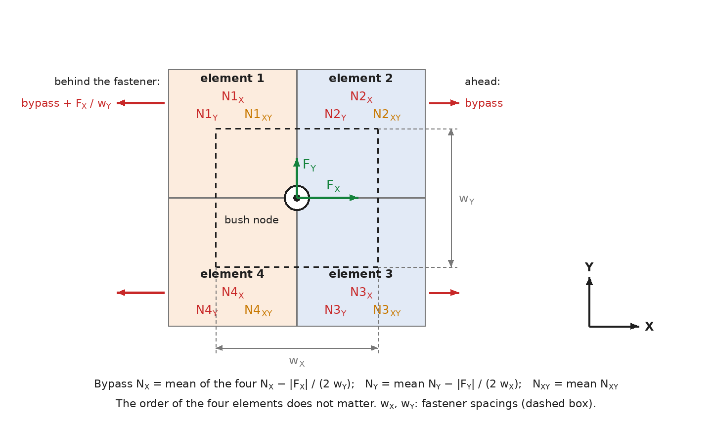
The order of the four elements does not matter. As a check the page prints the largest difference between the four elements beside F / w; the two should be of the same size.
Strains, when entered, are turned to the laminate axes and multiplied by the laminate stiffness: Nx = t (Ex εx + νxy Ey εy) / (1 − νxy νyx), Ny = t (νxy Ey εx + Ey εy) / (1 − νxy νyx), Nxy = t Gxy γxy.
Bearing toward −x or −y
The paper's factors are written for bearing toward +x and +y. The laminate is orthotropic, so a mirror image about either axis is the same problem: for bearing toward −x points 1 and 5, 2 and 4, 8 and 6 change places and the shear changes sign; for bearing toward −y points 2 and 8, 3 and 7, 4 and 6 change places. The page does this and reports the true point numbers.
Where the page departs from the printed paper
- Tension parallel to the crack. Table II prints + 0.97 exp(−4.169 u) with "minimum value 0". Only − 0.97, capped at 0 from above, gives f(0) = 1.13 Kt, the paper's own condition, and the negative stress intensity that tension parallel to a crack at a hole produces. The page uses the corrected sign.
- Bearing at the 45° points. Table II gives f̂(0) = 0.853, but Table IV divides Kt by 0.52 for these points, and f(0) = 1.13 Kt then needs f̂(0) = 0.588. The 0.52 is right: it is the isotropic value of the pin-loaded hole (Bickley). The page uses the expression as printed by default, which gives the higher stress, and offers a corrected form (exponential coefficient 0.182) that satisfies the condition and reproduces the paper's Figures 8 to 10 for load along the 0° direction.
- Table XVI. Four of its five printed Kt column heads do not follow the paper's Table III expression; the page uses the expression.
What it assumes, and its limits
- A balanced, symmetric laminate that behaves as a homogeneous orthotropic plate; the bearing pressure is a cosine distribution; fastener clamp-up, friction and hole clearance are not modeled.
- The author checked the model against forty-eight room-temperature tests of one T300/5208 laminate of half 0° and half ±45° plies with a 0.375 in untorqued fastener in double shear, under tension and bearing. Compression bypass has no test behind it.
- For load along the 0° direction the page reproduces the paper's predicted curves within a few percent. For bearing at an angle to the 0° direction it gives strengths up to about 25 percent below the paper's plotted curves, which are themselves below the tests: the page errs on the low side there.
- The bearing stress concentration fits and the finite-width tables come from laminates of 0° and ±45° plies. For laminates with 90° plies they are entered by Kt, an approximation the paper suggests but did not test.
- The check is of the stresses at the hole boundary. Net tension, shear-out, fastener shear and bending, pull-through, countersinks, fatigue and environment are outside it.