Tools › Electrical and Controls › Circuits › Circuit Analysis (DC and AC) › Method
Circuit Analysis (DC and AC): Method
Open the Circuit Analysis (DC and AC) tool
Method, Sign Conventions, Assumptions and Common Mistakes
What the tool does
You describe a circuit as a short table (which element sits between which two nodes) and the tool finds the voltage of every node and the current and power of every element, for constant (DC) sources or for sinusoidal (AC) sources of one frequency. It shows the equations it solved, so the page can be checked line by line against a hand solution.
How to enter a circuit
A node is a junction: every point joined by plain wire is one node. Give each node a short name of letters and digits (0, a, b, out). One node is the ground, the point from which every voltage is measured; any node may be chosen, and the negative terminal of the source is the usual choice. Each row of the table is one element between a + node and a − node:
• Voltage source: the + node is its positive terminal. • Current source: its arrow points to the + node, so, like a battery, it pushes current out of its + node. • Resistor, capacitor, inductor: the two nodes may be given in either order; the order only decides which direction of current is printed as positive.
Values are in ohms, farads, henries, volts and amperes, with the usual prefixes accepted: 4.7k, 2.2M, 10m, 100u (or 100μ), 100n, 47p, or 1e-6. The results name the elements by kind in table order: R1, R2, …, C1, …, L1, …, V1, …, I1, … A voltage source of 0 V is an ammeter: it reports the current through it and changes nothing.
The idea: one equation per node
Kirchhoff's current law says that charge does not pile up at a junction: the current flowing into a node equals the current flowing out. Ohm's law gives the current of each resistor from the voltages at its two ends. Writing the current law at every node except ground, with each current expressed through the node voltages, gives exactly as many equations as there are unknown voltages.
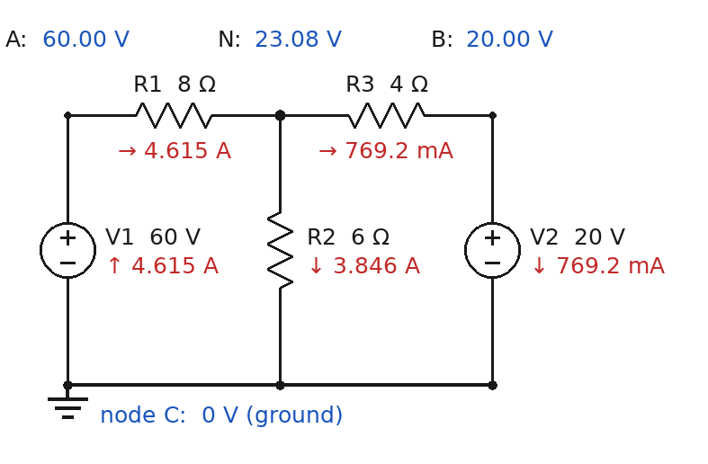
In Figure 1 the only unknown is VN, because the two batteries fix VA = 60 V and VB = 20 V. The currents leaving node N through the three resistors must add to zero:
(VN − 60) / 8 + VN / 6 + (VN − 20) / 4 = 0 ⇒ 13 VN = 300 ⇒ VN = 23.08 V
Every other answer follows from Ohm's law: 36.92 V across R1 drives 4.615 A, 23.08 V across R2 drives 3.846 A, and the difference, 0.769 A, flows into the positive terminal of the 20 V battery, which is therefore being charged. The tool reproduces the handbook's printed values (the handbook prints the first current as 4.65 A, a misprint of 36.923 / 8 = 4.615 A).
The equations
Node equations. For each node n except ground, summing over the elements attached to it: Σ (Vn − Vm) / R = currents delivered into the node by sources. A current source contributes its known current. A voltage source contributes an unknown current i and, in exchange, one more equation: V+ − V− = its voltage. This bookkeeping is called modified nodal analysis; it is what circuit simulators use, and it never needs the "supernode" trick of hand analysis.
Matrix form. Collected, the equations read A x = z, where x lists the node voltages followed by the voltage-source currents. A resistor R between nodes n and m adds 1/R to the two diagonal entries (n, n) and (m, m) and subtracts 1/R from the entries (n, m) and (m, n). The system is solved by Gaussian elimination with partial pivoting.
DC steady state. With constant sources and all transients over, a capacitor carries no current (an open circuit) and an inductor has no voltage (a short circuit, which the tool treats as a 0 V source so that its current is found).
AC steady state. With sinusoidal sources of one angular frequency ω = 2πf every voltage and current is a sinusoid of that frequency, described by a phasor: a complex number whose magnitude is the size and whose angle is the phase. The same node equations hold with impedances in place of resistances:
ZR = R, ZL = jωL, ZC = 1 / (jωC) = −j / (ωC)
Power. DC: P = V I for every element; resistors absorb I²R. AC with rms values: the complex power is S = V I* = P + jQ, where P (watts) is the average power, Q (var) the reactive power that sloshes between the source and the inductors (Q > 0) or capacitors (Q < 0), |S| (VA) the apparent power, and P / |S| the power factor. With peak values each of these is halved. In every solved circuit the power the sources supply equals the power the other elements absorb; the page prints both as a check.
Thévenin and Norton equivalent. Seen from any two terminals, a linear circuit behaves like one voltage source Vth in series with one resistance Rth (impedance Zth in AC). Vth is the voltage across the open terminals. Rth is found with every source set to zero (voltage sources replaced by wires, current sources removed) by driving 1 A through the terminals and reading the voltage. The Norton form is a current source IN = Vth / Rth in parallel with Rth. When you name an element, that element is removed and becomes the load; when you name two nodes, nothing is removed. A load RL then carries I = Vth / (Rth + RL).
Maximum power transfer. A load draws the most power when RL = Rth, namely Pmax = Vth² / (4 Rth). In AC the best load is the conjugate ZL = Zth*, giving |Vth|² / (4 Re Zth) for rms values; if the load must be a plain resistor the best is RL = |Zth|.
Two results worth recognizing. A series R-L-C circuit is at resonance when ωL = 1/(ωC), that is ω0 = 1 / √(LC): the two reactances cancel, the current is V/R, and the capacitor and inductor voltages are each Q = ω0L / R times the source voltage, which can be far larger than the source. A resistor feeding a capacitor is a low-pass filter whose output has fallen to 1/√2 = 0.707 of the input, 45° behind it, at the corner ω = 1 / (RC).
Sign conventions
The voltage of an element is V(+ node) − V(− node). The current of a resistor, capacitor or inductor is positive from its + node to its − node through the element, so the power it absorbs is V I. The current of a source is the current it delivers out of its + node, so the power it supplies is V I; a negative value means the source is absorbing power (a battery being charged). In the DC drawing each arrow shows the actual direction of flow; in the AC drawing the arrows show the reference directions, because an alternating current has no single direction.
What it assumes
Ideal, linear, lumped elements: resistors that obey Ohm's law at any current, capacitors and inductors without loss, sources that hold their voltage or current whatever is connected, wires without resistance. Steady state only: DC long after switching, or AC after the start-up transient has died away, with every source at the same frequency. Independent sources only.
When it misleads
• Real sources sag. A battery or bench supply has internal resistance; add it as a series resistor if the load is heavy. • Real inductors and capacitors have loss. At resonance the ideal model can print voltages that a real coil's resistance would never allow; add the coil resistance in series. • Not for switching or start-up. The moment after a switch closes is a transient problem; this page gives only the final state. • Not for diodes, transistors, op-amps or dependent sources. Those need a nonlinear or controlled-source model. • Sources of different frequencies cannot share one phasor solution: solve once per frequency and add the results in time, never as phasors. • Ratings are not checked. The page reports the power in each resistor but does not know its wattage rating, the voltage rating of a capacitor or the safe current of a wire.
Common mistakes in hand solutions
• Sign of a current at a node. Decide once that every term is a current leaving the node, (Vnode − Vother end) / R, and never switch. • Forgetting that the ground node is a node. Its equation is not written, but currents do return through it. • Writing a node equation through a voltage source. The current of a voltage source is not (Va − Vb) / R; it is an unknown, or the two nodes are tied by Va − Vb = V. • Current source direction. The arrow points to the node that receives the current. • Thévenin resistance with the sources left on. Voltage sources become wires and current sources become open circuits before Rth is found, and the load is removed first. • Adding magnitudes of phasors. In AC, 60 V across a resistor and 80 V across a capacitor in series make 100 V, not 140 V; add the complex numbers. • Hz against rad/s. The 1000 in 10 cos(1000 t) is ω in rad/s, which is 159.2 Hz. • rms against peak. A 120 V outlet is 120 V rms, 170 V peak; P = V I cos θ uses rms values. • Calling a capacitor a short in DC. In DC steady state the capacitor is the open circuit and the inductor the short. • Mixing mA with kΩ. Volts over kilohms give milliamperes; keep a consistent set or convert everything to base units.
Checks behind this page
The solver is tested against the printed worked examples of the DOE Fundamentals Handbook, Electrical Science (DOE-HDBK-1011-92): the series circuits, voltage divider, current division, Kirchhoff, loop-equation, node-voltage, series-parallel and bridge examples of Volume 1, Module 2, and the reactance, impedance and power examples of Volume 3, Modules 8 and 9. It is also compared with an independent solution written with a different formulation (all branch currents and node voltages as unknowns, solved by numpy) on 80 seeded random DC and AC circuits, including the Thévenin equivalent found there from the open-circuit voltage and the short-circuit current. The "Wheatstone bridge", "Thévenin seen by a load", "Series RLC at resonance" and "RC low-pass" cases of the Try this bar are illustrative circuits with round numbers, checked against their closed forms; the "Voltage divider" and "Two batteries, one node" cases are the handbook's Figures 29 and 45.