Tools › Structures › Stress Concentrations › Round Hole Uniaxial Stress › Method
Round Hole Uniaxial Stress: Method
Open the Round Hole Uniaxial Stress tool
Round Hole in an Infinite Plate under Uni-axial Load: the Kirsch Solution
Problem Statement
A large, thin, flat plate contains a circular hole of diameter D (radius a = D/2) and carries a uniform uni-axial stress σx far from the hole. The plate is linear elastic, isotropic and in plane stress, and it is "infinite": every edge is far enough from the hole that it does not disturb the stress field (in practice, a plate width and length of more than about 10 hole diameters, with the hole at least 5 diameters from any edge). The question is the state of stress at a point P near the hole, given by its distance r from the hole center and the angle θ between the radius to P and the load axis.
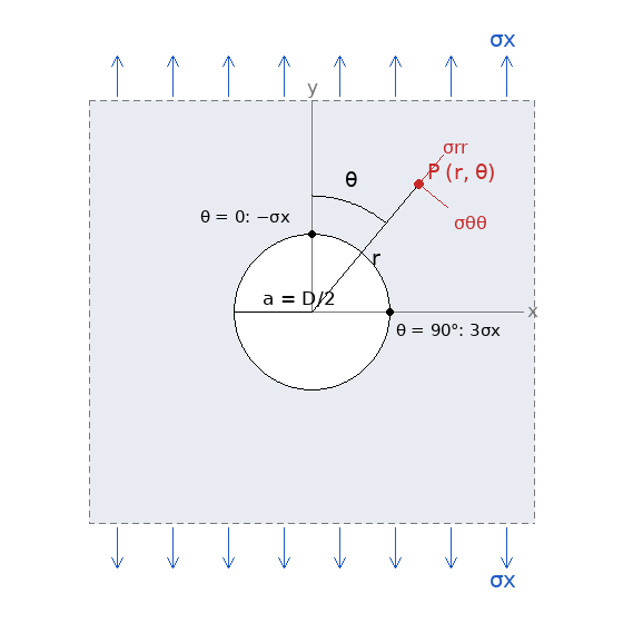
Figure A: Convention used by the tool. The load σx acts along the vertical y axis; θ is measured from that axis to the radius through P; σrr acts along the radius and σθθ across it.
Key Assumptions
Infinite plate, linear elastic, plane stress, uni-axial load. The plate edges are far from the hole; the material is isotropic and stays elastic (no yielding at the 3σx peak); the plate is thin enough that through-thickness stresses are negligible; the hole is open (no fastener or pin) and traction-free. The solution does not depend on the elastic constants, so the stresses are the same for every isotropic material.
Solution
Kirsch (1898) solved the problem with an Airy stress function in polar coordinates. The uniform far-field stress is split into a hydrostatic part σx/2, which the hole disturbs through the axisymmetric terms, and a pure-shear part (σx/2) cos 2θ, which the hole disturbs through the cos 2θ terms. The stress function
Φ = (σx/4) (r² − 2a² ln r) − (σx/4) (r² − 2a² + a⁴/r²) cos 2θ
satisfies the biharmonic equation, gives the uniform stress at r → ∞, and makes the hole edge traction-free (σrr = σrθ = 0 at r = a). Differentiating it gives the stresses the tool evaluates:
σrr = (σx/2) (1 − a²/r²) + (σx/2) (1 − 4a²/r² + 3a⁴/r⁴) cos 2θ
σθθ = (σx/2) (1 + a²/r²) − (σx/2) (1 + 3a⁴/r⁴) cos 2θ
σrθ = −(σx/2) (1 + 2a²/r² − 3a⁴/r⁴) sin 2θ
The tool writes the radial and shear coefficients in factored form, (1 − a²/r²)(1 − 3a²/r²) and (1 − a²/r²)(1 + 3a²/r²), which multiply out to the expressions above and show at a glance that both vanish on the hole edge. This is Kirsch's own notation: page 799 of the 1898 paper prints the equations in exactly this form, with the angle measured from the load axis and the load drawn vertical in his Fig. 5, which is the convention of Figure A.
Hole Edge and Stress Concentration Factor
On the free edge r = a only the tangential stress survives:
σθθ(a, θ) = σx (1 − 2 cos 2θ)
- θ = 90° and 270° (the sides of the hole, on the axis normal to the load): σθθ = 3σx. This is the maximum stress in the plate, so the stress concentration factor of a round hole in an infinite plate is Kt = 3, independent of the hole size and of the material.
- θ = 0 and 180° (the top and bottom of the hole, on the load axis): σθθ = −σx. A tensile load puts the top and bottom of the hole into compression of the same magnitude as the applied stress.
- The tangential stress changes sign where cos 2θ = 1/2, i.e. at θ = 30° from the load axis.
The disturbance decays quickly: along the axis normal to the load, σθθ/σx = 1 + a²/(2r²) + 3a⁴/(2r⁴), which is 1.22 at r = 2a and 1.07 at r = 3a. That is why a hole can be treated as "in an infinite plate" when the edges are a few diameters away.
Principal Stresses at the Probed Point
Away from the edge all three polar components are non-zero, and the tool transforms them to principal values with the plane-stress relations:
σmax, σmin = (σrr + σθθ)/2 ± √[((σrr − σθθ)/2)² + σrθ²]
τmax = √[((σrr − σθθ)/2)² + σrθ²] = (σmax − σmin)/2
tan 2φp = 2σrθ / (σrr − σθθ)
φp is measured from the radial direction. The arctangent gives two directions 90° apart, one for each principal stress; the tool picks the one belonging to σmax (when σθθ > σrr the arctangent branch locates σmin, so 90° is added) and keeps it within ±90°. φx = φp + θ gives the same direction from the load axis. On the hole edge, where σrr = σrθ = 0, the principal directions are simply radial and tangential. The in-plane τmax is the quantity to compare with a shear allowable; the absolute maximum shear stress, which includes the out-of-plane direction, is σmax/2 when both in-plane principal stresses are positive.
Reading the Plots
- σθθ fringe. Shows the Kirsch component the equations compute. The 3σx lobes at the sides and the −σx spots at the top and bottom are real; the X-shaped pattern far from the hole is not a stress concentration but the far-field value σθθ → σx sin²θ, which is just the uniform stress resolved onto a rotating direction.
- σmax fringe. Shows stress severity. The far field is uniform σx, the lobes are the same, the top and bottom of the hole read zero because the compression there is σmin, and the cyan "stress shadow" above and below the hole is where the load flows around the hole and σmax drops below σx.
- Line plots. The edge curve σx(1 − 2 cos 2θ) and the decay along the two axes; the user input point is marked where it lies on the plotted line.
Limits of the Solution
- Finite width. When the plate width W is not large compared with D, the net-section stress rises and Kt based on the gross stress falls below 3 while Kt based on the net stress rises above it. Howland (1930) solved the strip; Heywood's fit Kt,net = 2 + (1 − D/W)³ is the usual design form and the charts in Peterson's Stress Concentration Factors cover D/W up to 0.6. This tool does not apply a finite-width correction.
- Biaxial load. The solution is linear, so a second remote stress is handled by superposition: equal biaxial tension gives Kt = 2, pure shear (equal and opposite stresses) gives Kt = 4.
- Yielding. A 3σx peak reaches the yield strength at σx = Fty/3; beyond that the elastic solution overstates the peak stress and a Neuber or Glinka estimate is needed.
- Loaded holes (pins, fasteners) have a different field; see the fastened-joint tools.