Tools › Structures › Stress Concentrations › Round Hole General Load › Method
Round Hole General Load: Method
Open the Round Hole General Load tool
Round Hole in an Infinite Plate under General In-plane Load
Problem Statement
A large, thin, flat plate with a round hole of diameter D (radius a = D/2) carries a uniform in-plane membrane state far from the hole, given as the stress resultants Nxx, Nyy, Nxy (force per unit width) and the plate thickness t. The far-field stresses are σxx∞ = Nxx/t, σyy∞ = Nyy/t, τxy∞ = Nxy/t. The plate is linear elastic, isotropic, in plane stress and infinite (edges far from the hole). The question is the stress at a point P(r, θ), θ measured from the y axis towards x, and the extremes on the hole edge.
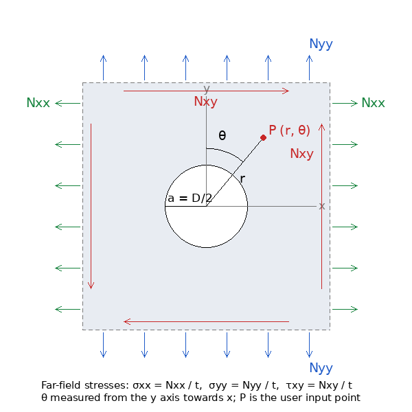
Figure A: Convention. Nxx and Nyy are positive in tension; Nxy is positive when it acts in +x on the top (+y) edge; θ is measured from the y axis towards x, the same convention as the uni-axial tools, where y is the load axis.
Key Assumptions
Infinite plate, linear elastic, plane stress, uniform far field. The resultants are uniform and the plate thin, so N/t is a uniform membrane stress with no bending. The hole is open and traction-free. The material stays elastic at the peak. The solution does not depend on the elastic constants.
Solution by Superposition
The Kirsch solution is linear in the remote stress. Resolve the far-field state into its principal values and direction,
S1,2 = (σxx∞ + σyy∞)/2 ± √[((σxx∞ − σyy∞)/2)² + (τxy∞)²], tan 2φ = 2τxy∞ / (σxx∞ − σyy∞),
and add the uni-axial Kirsch fields for S1 and S2. Written directly in the plate axes, with q = a²/r², the mean stress Sm = (σxx∞ + σyy∞)/2 and the deviatoric terms resolved on the radius at θ,
D(θ) = −(σxx∞ − σyy∞)/2 · cos 2θ + τxy∞ sin 2θ, E(θ) = (σxx∞ − σyy∞)/2 · sin 2θ + τxy∞ cos 2θ,
the stresses are
σrr = Sm (1 − q) + D(θ) (1 − 4q + 3q²)
σθθ = Sm (1 + q) − D(θ) (1 + 3q²)
σrθ = E(θ) (1 + 2q − 3q²)
The signs follow the tool's convention (θ from y towards x, tangential direction in the sense of increasing θ). With σyy∞ = σx and the other two zero, D = (σx/2) cos 2θ, E = −(σx/2) sin 2θ, and the equations reduce to those of the uni-axial tool. The tool checks its plots, which use the superposed complex-potential field of the elliptic tool with a = b, against these closed forms.
Hole Edge and Stress Concentration Factor
On the edge q = 1 and only the hoop stress remains: σθθ(a, θ) = (σxx∞ + σyy∞) − 4D(θ). Since D swings between ±(S1 − S2)/2, the extremes are
- σedge,max = 3S1 − S2, at the two points where the S2 axis meets the hole (perpendicular to S1);
- σedge,min = 3S2 − S1, at the two points on the S1 axis.
Reference for Kt. There is no single applied stress, so the tool refers Kt to the maximum far-field principal stress: Kt = σedge,max/S1 = 3 − S2/S1. Uni-axial: 3. Equal biaxial tension: 2 (the hoop stress is 2S all round). Pure shear (S2 = −S1 = −τ): 4, at 45° to the shear axes. Biaxial tension lowers the peak; a compressive S2 raises it. When the far field has no tensile principal stress (S1 ≤ 0) the ratios are formed with S2 instead, so that the governing compressive peak is compared with the governing far-field compression.
Principal Stresses at the Probed Point
From σrr, σθθ, σrθ the tool gives σmax, σmin, τmax and the direction of σmax both from the y axis (φx) and from the radial direction (φp), each within ±90°. The direction of S1 is reported in the same way (φ1, from the y axis).
Reading the Plots
- σθθ fringe. The tangential stress about the hole center; on the edge it is the hoop stress, whose extremes sit on the far-field principal axes rather than on x and y. The color scale spans those two extremes in units of the reference stress.
- σmax fringe. The maximum principal stress, uniform S1 far from the hole.
- Line plots. The hoop stress around the edge versus θ, and the stresses along the x and y axes versus r/a. Under a general load these axes are not the principal axes, so the edge extremes appear in Figure 3 but not necessarily at the start of Figures 4 and 5.
Limits
- Finite width and yielding: as for the uni-axial tool; no finite-width correction is applied, and the elastic peak is valid up to σedge,max = Fty.
- Bending (Mxx, Myy, Mxy) is a different problem (Goodier, Reissner); only membrane resultants are handled here.