Tools › Structures › Stress Concentrations › Elliptic Hole Uniaxial Stress › Method
Elliptic Hole Uniaxial Stress: Method
Open the Elliptic Hole Uniaxial Stress tool
Elliptic Hole in an Infinite Plate under Uni-axial Load: the Inglis Solution
Problem Statement
A large, thin, flat plate contains an elliptic hole with semi-axis a across the load and semi-axis b along it, and carries a uniform uni-axial stress σx far from the hole. The plate is linear elastic, isotropic and in plane stress, and "infinite": every edge is far enough from the hole not to disturb the stress field. The question is the state of stress at a point P, given by its distance r from the hole center and the angle θ between that radius and the load axis, and the stress concentration at the hole edge. With a = b the hole is round and everything reduces to the Kirsch solution of the companion tool.
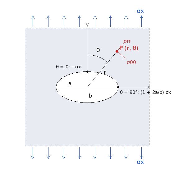
Figure A: Convention used by the tool. The load σx acts along the vertical y axis; a is the semi-axis across the load (along x), b the semi-axis along the load; θ is measured from the load axis to the radius through P.
Inclined hole. The input β rotates the hole: it is the angle of the semi-axis a from the horizontal, positive counterclockwise towards the load axis, so Figure A shows β = 0 and β = 90° puts a along the load (the same as swapping a and b). The probe angle θ is always measured from the load axis in the plate frame, not from the hole's axes.
Key Assumptions
Infinite plate, linear elastic, plane stress, uni-axial load. The hole may be aligned with the load or inclined to it by β; an inclined hole has an unsymmetric field whose edge extremes the tool finds by scanning the edge. The material stays elastic at the peak, the plate is thin, and the hole is open and traction-free. The solution does not depend on the elastic constants.
Solution
Inglis (1913) solved the problem in elliptic coordinates; the equivalent and more compact form, due to Kolosov and Muskhelishvili, uses two analytic functions of a complex variable and a conformal map. The exterior of the unit circle |ζ| ≥ 1 is mapped onto the plate outside the hole by
z = x + iy = ω(ζ) = R (ζ + m/ζ), R = (a + b)/2, m = (a − b)/(a + b),
which takes the unit circle onto the ellipse (m = 0 is the circle, m → 1 the straight crack). For a remote tension p = σx at angle α to the a axis the potentials are
φ(ζ) = (pR/4) [ζ + A/ζ], A = 2e2iα − m
ψ(ζ) = −(pR/4) [1/ζ + Āζ] − (pR/4) (1 + mζ²)(ζ² − A) / [ζ(ζ² − m)]
The tool works in the hole's own frame, where the load direction makes α = 90° − β with the a axis; for the aligned hole α = 90° and A = −(2 + m). φ is fixed by the uniform stress at infinity; ψ follows from the traction-free hole through ψ(ζ) = −φ̄(1/ζ) − ω̄(1/ζ) φ′(ζ)/ω′(ζ), and its linear term at infinity confirms A. The stresses are the Kolosov formulas
σxx + σyy = 4 Re Φ(ζ), σyy − σxx + 2iτxy = 2 [z̄ Φ′(ζ) + ψ′(ζ)] / ω′(ζ), Φ = φ′(ζ)/ω′(ζ).
For a point P the tool rotates its coordinates into the hole's frame, finds ζ from z by solving the quadratic Rζ² − zζ + Rm = 0 for the root with |ζ| ≥ 1, evaluates the formulas above, rotates the stress tensor back to the plate frame, and then into the polar components σrr, σθθ, σrθ about the hole center and into principal stresses. With m = 0 the formulas give the Kirsch stresses exactly (the tool's test cases check this to machine precision).
Hole Edge and Stress Concentration Factor
On the free edge the normal and shear stresses vanish and the hoop stress equals σxx + σyy = 4 Re Φ. Its extremes are at the ends of the axes:
- θ = 90° and 270°, the ends of the semi-axis a across the load: σ = σx (1 + 2a/b), so Kt = 1 + 2a/b. With the radius of curvature at those ends, ρ = b²/a, this is Kt = 1 + 2√(a/ρ), the form carried over to notches and cracks.
- θ = 0 and 180°, the ends of the semi-axis b on the load axis: σ = −σx, whatever the shape.
For an inclined hole the extremes leave the axis ends and no simple closed form exists; the tool evaluates the hoop stress around the whole edge (3600 points, refined by a golden-section search) and reports the largest and the most compressive value with the polar angle of each. The largest value lies between the end of a and the direction across the load and is smaller than 1 + 2a/b; the compressive extreme can exceed σx in magnitude (for a = 2b at β = 30°: 4.33σx and −1.08σx). With β = 90° the roles of a and b swap and Kt = 1 + 2b/a.
A hole elongated across the load (a > b) concentrates stress more than a round hole; elongated along the load (a < b) it concentrates less, down to Kt → 1 for a slit parallel to the load. For a = 2b, Kt = 5; for a = 10b, 21. As b → 0 the factor grows without bound: the stress at the tip of a sharp crack is not described by a concentration factor but by the stress intensity factor of fracture mechanics, which Griffith built on this solution.
Principal Stresses at the Probed Point
The tool transforms σxx, σyy, τxy at P to σmax, σmin = (σxx + σyy)/2 ± √[((σxx − σyy)/2)² + τxy²], τmax = the root, and the direction of σmax, given both from the load axis (φx) and from the radial direction through P (φp), each kept within ±90°. On the edge the principal directions are normal and tangential to the ellipse, which coincide with radial and tangential only at the ends of the axes.
Reading the Plots
- σηη fringe. The tangential stress along the confocal ellipses through each point, the counterpart of σθθ for the round hole; on the edge it is the hoop stress. Far away it tends to the uniform stress resolved onto the local tangent, which gives the X-shaped background.
- σmax fringe. Stress severity: the peaks at the ends of a, zero at the ends of b (the compression there is σmin), the stress shadow above and below the hole, the uniform σx far field.
- Line plots. The hoop stress around the edge against the polar angle of the edge point, and the stresses along the two axes against x/a and y/b; the user input point is marked where it lies on the plotted line.
Limits of the Solution
- Finite width raises the net-section stress; Peterson's charts give the correction. Not applied here.
- Biaxial load. The solution is linear, so a second remote stress is handled by superposition of two solutions with different α; the tool computes one uni-axial load.
- Yielding. The peak reaches Fty at σx = Fty/Kt; beyond that the elastic solution overstates it.
- Very slender holes (a/b above about 20) approach the crack and the map becomes ill-conditioned near the tips; use fracture mechanics there.