Tools › Structures › Plates and Shells › Plate Bending › Method
Plate Bending: Method
Plate Bending: Navier and Lévy Series, the Clamped-Plate Superposition and the Circular-Plate Closed Forms
What the tool computes
The small-deflection (Kirchhoff) bending of a flat plate: the deflection surface w(x, y), the bending and twisting moments per unit width Mx, My, Mxy, the bending stresses on the two faces, the edge reactions and the concentrated corner forces, for a rectangular plate with any combination of simply supported and clamped edges (and free edges opposite a simply supported pair), under a uniform, linearly varying, patch, line or point load; and for solid circular and annular plates under a uniform load, a central or inner-edge load and an edge moment. Margins of safety are given against an allowable stress and a deflection limit. The theory is Timoshenko and Woinowsky-Krieger's Theory of Plates and Shells (1959), Chapters 3 to 6, and the page reproduces the coefficients of its Tables 8 and 35 beside the series values.
Conventions
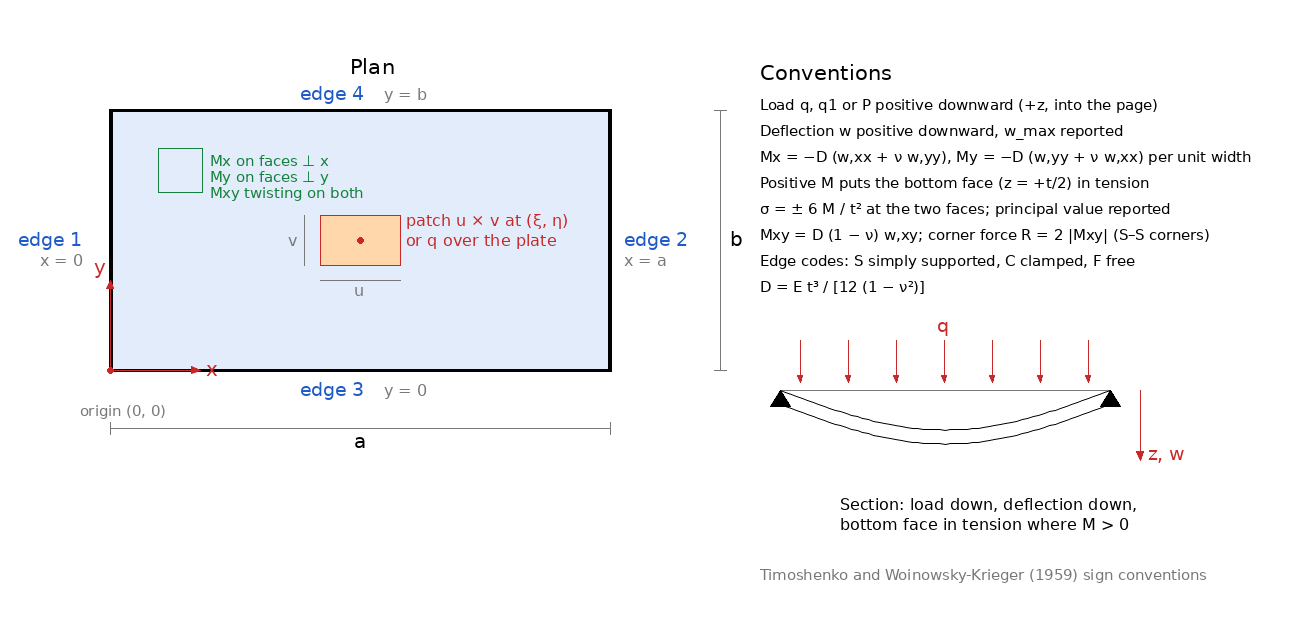
Rectangular plate 0 ≤ x ≤ a, 0 ≤ y ≤ b; edges 1 (x = 0), 2 (x = a), 3 (y = 0), 4 (y = b). Loads and deflections are positive downward (+z). The flexural rigidity is D = E t3/[12(1 − ν2)]. Moments per unit width follow Timoshenko: Mx = −D(w,xx + ν w,yy), My = −D(w,yy + ν w,xx), Mxy = D(1 − ν)w,xy; a positive Mx bends the plate concave upward and puts the bottom face (z = +t/2) in tension. The surface stresses are σx = ±6Mx/t2, σy = ±6My/t2, τxy = ±6Mxy/t2, and the tool reports the largest principal value on either face. The Kirchhoff edge reactions are Vx = −D[w,xxx + (2 − ν)w,xyy] and Vy likewise; at a corner where both edges are simply supported a concentrated force R = 2Mxy is needed to hold the corner down (Timoshenko Art. 22 and 30).
The governing equation
With the Kirchhoff hypotheses (straight normals, no transverse shear strain, no mid-plane stretching) the equilibrium of a plate element under a transverse load q(x, y) reduces to the biharmonic equation D∇4w = q (Lagrange, 1811). Two conditions apply on each edge: simply supported w = 0, Mn = 0; clamped w = 0, ∂w/∂n = 0; free Mn = 0, Vn = 0 (Kirchhoff's two conditions replacing Poisson's three). Every result on the page is an exact solution of this problem, summed to convergence; no finite-element approximation is involved.
Navier's double series (all edges simply supported)
Navier (1823) expanded both the load and the deflection in a double sine series, w = ΣΣ wmn sin(mπx/a) sin(nπy/b), which satisfies the simply supported conditions term by term; substitution in the plate equation gives wmn = pmn/[π4D(m2/a2 + n2/b2)2] with pmn = (4/ab)∫∫ q sin sin dx dy (Timoshenko Art. 28 and 29). For a uniform load pmn = 16q/(π2mn) over odd m, n; for a load P spread over a u × v patch at (ξ, η) it is 16P/(π2mnuv) sin(mπξ/a) sin(nπη/b) sin(mπu/2a) sin(nπv/2b), which tends to the point-load value 4P/(ab) sin sin as the patch shrinks. The deflection converges like 1/N4 and the moments like 1/N2 in the number of terms, so the page prints the centre values at 5, 15, 45 and 135 terms per direction as the convergence record.
Lévy's single series (two opposite edges simply supported)
Lévy (1899) kept the sine series along x only, w = Σ Ym(y) sin(αmx), αm = mπ/a, so that edges 1 and 2 are simply supported identically and each harmonic obeys the ordinary equation Y'''' − 2α2Y'' + α4Y = pm(y)/D, where pm(y) is the m-th sine coefficient of the load. Its solution is a particular part plus four exponential terms whose constants follow from the two conditions on each of the edges 3 and 4, which may each be simply supported, clamped or free (Timoshenko Art. 30, 31, 41, 46 and 48). The tool writes the four terms on the scaled basis e−αy, e−α(b−y), ye−αy, (b − y)e−α(b−y), so that the 4 × 4 system of every harmonic is well conditioned however many harmonics are taken. The particular part of a distributed load (uniform or linearly varying) is summed in closed form: the sum over m is the cylindrical bending of a strip simply supported at x = 0 and x = a, wp = q(x4 − 2ax3 + a3x)/(24D) for the uniform load, so the series carries only the exponentially decaying edge corrections and the slow 1/m3 tail of the moments disappears. For a patch, line or point load at y = η the particular part is the response of the infinite strip to the load's m-th harmonic, (1 + α|y − η|)e−α|y−η|/(4Dα3) per unit of line load, integrated across the patch; its moments converge like 1/m2, so 240 harmonics are used for those loads.
The free-edge conditions are Y'' − να2Y = 0 (zero My) and Y''' − (2 − ν)α2Y' = 0 (zero Kirchhoff shear Vy). A free edge is therefore available on edges 3 and 4 only; a plate with a free edge at x = 0 or x = a is entered rotated.
Clamped edges on the Lévy direction: Timoshenko's superposition
When edge 1 or 2 is clamped no single series satisfies the conditions, and the tool follows Timoshenko's method for the plate with all edges built in (Art. 44): the simply supported Lévy solution of the load is superposed with sine-series bending moments applied along every clamped edge, My(x, 0) = Σ Em sin(αmx) on edge 3 and so on, each of which is itself a Lévy solution (in x for edges 3 and 4, in y for edges 1 and 2). The coefficients are found from the requirement that the slope normal to each clamped edge vanish, harmonic by harmonic. The slope along edge 3 produced by the moments on edge 1 is a function of x that must be re-expanded in sin(αmx): the tool evaluates these cross terms in closed form (integrals of exponentials times sines), assembles the dense linear system for all the edge-moment coefficients (40 harmonics along x, in proportion along y) and solves it directly. The fixing moment along a clamped edge is then the applied series itself, and the slope conditions are satisfied to about 10−6 of the plate's curvature. Any combination of simply supported and clamped edges is handled this way; the simply supported pair on edges 1 and 2 reduces it to the plain Lévy solution.
Circular and annular plates
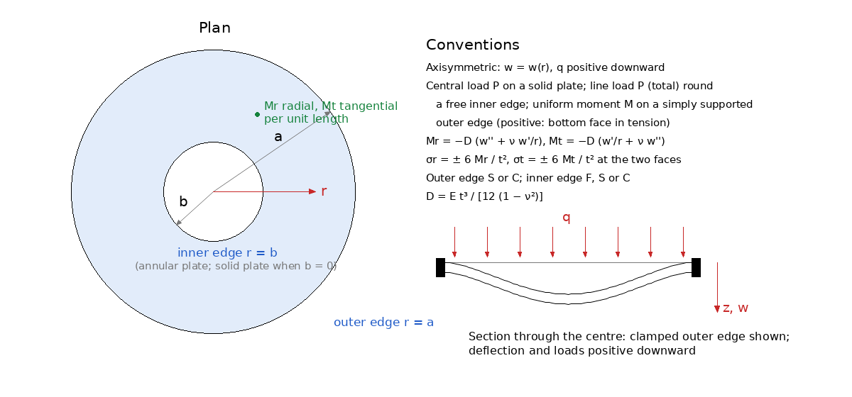
For axisymmetric bending the plate equation becomes an ordinary one in r whose general solution is w = C1 + C2r2 + C3 ln(r/a) + C4r2 ln(r/a) + qr4/(64D) (Timoshenko Chapter 3). For a solid plate C3 = C4 = 0 (finite deflection and slope at the centre) and the two outer-edge conditions give the classical results: a clamped plate under uniform load has w = q(a2 − r2)2/(64D), the maximum qa4/(64D) and the fixing moment −qa2/8; a simply supported plate has the maximum (5 + ν)qa4/[64(1 + ν)D] and the centre moment (3 + ν)qa2/16; a central load P gives Pa2/(16πD) clamped and (3 + ν)Pa2/[16π(1 + ν)D] simply supported, with a moment that grows like ln(a/r) toward the load; a uniform edge moment M on a simply supported plate bends it into a sphere with Mr = Mt = M and w = M(a2 − r2)/[2D(1 + ν)]. For an annular plate the four constants follow from two conditions at each edge (free: Mr = 0 and the shear equal to the applied line load; simply supported; clamped), solved as a 4 × 4 system; the moments are Mr = −D(w'' + νw'/r) and Mt = −D(w'/r + νw''). As the hole shrinks the deflection under an inner-edge line load tends to the central point-load value, while the tangential moment at the hole edge stays finite and large: a small hole is a stress raiser.
Timoshenko's coefficient tables
Timoshenko tabulated the results in the form wmax = α qa4/D, M = β qa2, R = n qa2, with a the shorter side and ν = 0.3: Table 8 for the simply supported plate (α = 0.00406, β = 0.0479, n = 0.065 for the square; 0.01013, 0.1017, 0.0464 for b/a = 2; 0.01302 = 5/384 and 0.125 for the infinite strip) and Table 35 for the clamped plate (0.00126, edge moment −0.0513, centre moment 0.0231 for the square). Those tables were computed with a few terms of the series, and the converged values differ from the printed ones by up to 0.6 % (the clamped plate's centre moments by about 1 %): the exact clamped-square values are 0.0012653, −0.05133 and 0.02291 (Taylor and Govindjee 2004), against the printed 0.00126, −0.0513 and 0.0231. The tool prints the table value beside the series value wherever the aspect ratio is tabulated, so a hand calculation from the book can be checked at a glance; Roark's Table 11.4 (cases 1a and 8a) carries the same coefficients in the form w = α qb4/(Et3), σ = β qb2/t2, that is 10.92α and 6β of Timoshenko's.
Reading the results
The deflection section gives the maximum and its location (the grid maximum refined by a parabolic search), the centre value and the coefficient α. The moment section gives the centre moments and their coefficients, the extremes of Mx and My on the evaluation grid, and the fixing moments at the mid-points of the clamped edges, which are the largest moments of a clamped plate and so govern its stress. The stress section gives the largest principal bending stress on either face and the moments at that point; the margin section checks it on both faces as described below. The reactions section lists the total reaction of each edge, the reaction per unit length at mid-edge, the corner forces and the equilibrium check: for a simply supported plate the edge reactions exceed the load by the corner forces, which hold the corners down (26 % of the load for the square, Timoshenko Art. 30); for two free edges the corners press on the supports instead and the sign is negative; next to a clamped edge the twisting moment vanishes and there is no corner force. The series-convergence tables show the centre values at increasing numbers of terms; the edge quantities are evaluated with the series extended to 600 harmonics because the twisting moment at a corner converges only like 1/m2.
Load level and factors of safety
The load-type radio says what the entered load is, ultimate or limit; the margin boxes name the level of their allowable, never of the entered load. The largest bending stress σb is tension on one face and compression on the other, so four fibre checks are made: the tension face against Ftu at ultimate load (ULT) and against Fty at limit load × FSyld (LIM); the compression face against Fcy at limit load × FSyld (LIM) and, because the face of a plate is a stable element that cannot cripple, against Fcy as its compression ultimate at ultimate load (ULT). With a limit load entered the strength checks multiply the stress by FS (default 1.5, the ultimate factor of 14 CFR 25.303) and the yield checks by FSyld (default 1.15, the factor several agencies require on limit load for no detrimental permanent set); with an ultimate load entered the strength checks use the stress as entered, never multiplied by FS, and the yield checks divide it by FS and multiply by FSyld, so FS stays active in both positions. The deflection limit is a limit-load check: the computed deflection is divided by FS when an ultimate load was entered. A plastic-bending (Cozzone) allowable is not offered: it is a whole-section check that needs the transverse-shear interaction, which the Cozzone tool provides.
Limits
- Thin plates. Kirchhoff theory neglects transverse shear deformation; it is good for a thickness below about a tenth of the shorter span. Thicker plates deflect more (Mindlin or Reissner theory).
- Small deflections. The theory ignores mid-plane stretching, which stiffens a plate whose deflection approaches its thickness: Levy's large-deflection solutions (NACA Reports 737 and 740, 1942) show the square simply supported plate's centre deflection at w/t = 1 to be about 70 % of the linear value, with membrane stresses added to the bending stresses. The page flags wmax/t above 0.5; beyond it the results are upper bounds on the deflection and the bending stress.
- Point loads. The deflection under a concentrated load is finite but the bending moment is logarithmically singular, so the reported maximum stress for a point load is a grid value that grows without bound as the grid is refined. Enter the real footprint of the load (u, v) or use Timoshenko's Art. 19 and 37 results for a load over a small circle.
- Edges. Ideal simple supports and clamps only; no elastic rotational restraint, no edge beams, no elastic foundation. A free edge is available opposite a simply supported pair only.
- Material. Homogeneous, isotropic, linearly elastic. Orthotropic and laminated plates are the province of the Classical Laminate Theory tool; the Hole in Plate Bending tool covers the stress concentration of a hole under plate bending.