Tools › Structures › Plates and Shells › Circular and Annular Plates › Method
Circular and Annular Plates: Method
Open the Circular and Annular Plates tool
Circular and Annular Plates: the Axisymmetric Plate Equation, its Exact Solution, the Edge Conditions and the Handbook Tables
What the tool computes
The small-deflection (Kirchhoff) bending of a solid circular plate or an annular plate (a plate with a concentric hole) under an axisymmetric load: the deflection w(r), the slope dw/dr, the radial and tangential bending moments per unit length Mr and Mt, the transverse shear per unit length Qr, the surface bending stresses and the edge reactions, at the centre or inner edge, at the outer edge and at a radius the analyst chooses, together with the largest deflection and the largest stress and where they occur. The loads are a uniform pressure, a central point load, a load spread over a central circle, a ring line load at any radius, a pressure growing linearly with the radius, a line load round the inner edge and moments on either edge. The outer edge may be simply supported, clamped or free and the inner edge free, simply supported, clamped or guided. A plate whose thickness varies linearly with the radius is solved numerically from the variable-rigidity equation. The results are written in the coefficient forms of Timoshenko and Woinowsky-Krieger's Table 3 and Roark's Table 11.2 so that a hand calculation from either book can be checked at a glance, and margins of safety are given against an allowable stress and a deflection limit.
Conventions
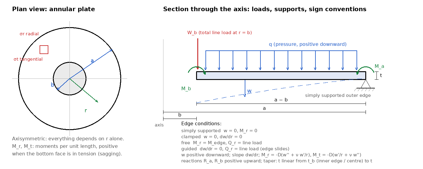
Radius r from the axis, inner radius b (zero for a solid plate), outer radius a, thickness t. Loads and the deflection w are positive downward. The flexural rigidity is D = E t3/[12(1 − ν2)]. With Timoshenko's definitions the moments per unit length are Mr = −D(w″ + ν w′/r) and Mt = −D(w′/r + ν w″), positive when they put the bottom face in tension (the plate sags), and the shear per unit length is Qr = −D d(w″ + w′/r)/dr; for a plate carried at its outer edge Qr = −(load inside r)/(2πr), so it is negative under a downward load. The surface stresses are σr = ±6Mr/t2 and σt = ±6Mt/t2; the radial and tangential directions are principal, so the largest of the two magnitudes is the largest bending stress. An edge moment is positive when it puts the bottom face in tension at that edge, i.e. Mr = +M there, on either edge. Edge reactions are positive upward.
The axisymmetric plate equation and its general solution
For a load that depends on the radius alone the plate equation D∇4w = q becomes the ordinary equation (Timoshenko and Woinowsky-Krieger, Art. 15, eq. 58)
(1/r) d/dr { r d/dr [ (1/r) d/dr ( r dw/dr ) ] } = q(r)/D,
whose homogeneous solution is w = C1 + C2r2 + C3 ln r + C4r2 ln r. A particular solution for a load law q = α + βr + γr2 is αr4/(64D) + βr5/(225D) + γr6/(576D), and for a central point load P on a solid plate the term P r2 ln(r/a)/(8πD) (Art. 19, eq. 86) supplies the shear −P/(2πr) near the centre. The tool writes the basis on r/a so that every constant has the dimension of a length. In a solid plate C3 = C4 = 0, because the deflection and the slope must stay finite at the centre, and the two remaining constants follow from the two conditions at the outer edge. In an annular plate all four constants are needed and the two conditions at each edge give a 4 × 4 linear system. When the load law changes at a radius ro (a load over a central circle, a ring line load) the plate is written as two regions with their own constants: at ro the deflection, the slope and the radial moment are continuous and the shear jumps by the line load, Qr(ro+) − Qr(ro−) = −W/(2πro) (Art. 19). The system is solved exactly by elimination; nothing is iterated or approximated, and the page prints the constants so that the solution can be evaluated by hand at any radius.
Edge conditions
- Simply supported: w = 0 and Mr = 0 (or the applied edge moment).
- Clamped: w = 0 and dw/dr = 0.
- Free: Mr = 0 (or the applied edge moment) and Qr equal to the applied line load per unit length; for an axisymmetric plate the twisting moment vanishes, so Kirchhoff's combined shear condition reduces to Qr.
- Guided: dw/dr = 0 and Qr equal to the applied line load. This is Roark's "guided" inner edge: the edge is held against rotation but free to move along the axis, as on a hub that slides on its shaft or a piston attached to a diaphragm. Two guided or free edges would leave the plate free to translate, so at least one edge must be simply supported or clamped.
A solid plate with a uniform moment on a simply supported edge bends into a sphere, w = M(a2 − r2)/[2D(1 + ν)], with Mr = Mt = M everywhere (Art. 15); on a clamped edge the moment is taken by the support and does nothing, and the tool refuses it. The same applies to a moment on a clamped or guided inner edge, and a line load on a simply supported or clamped inner edge goes straight into the support.
The classical solid-plate results
The two uniform-load cases and the two central-load cases are printed in Timoshenko's closed forms with the substituted numbers. Clamped, uniform load (Art. 15): w = q(a2 − r2)2/(64D), the maximum qa4/(64D) = 0.171 qa4/(Et3) at ν = 0.3, the fixing moment −qa2/8 (the largest moment, σ = 0.75 qa2/t2) and the centre moment (1 + ν)qa2/16. Simply supported, uniform load (Art. 16): the maximum (5 + ν)qa4/[64(1 + ν)D] = 0.696 qa4/(Et3), the centre moment (3 + ν)qa2/16 (σ = 1.24 qa2/t2), the edge tangential moment (1 − ν)qa2/8 and the edge slope −qa3/[8(1 + ν)D]. Central load P (Art. 19): the maximum Pa2/(16πD) = 0.217 Pa2/(Et3) clamped, with the fixing moment −P/(4π), and (3 + ν)Pa2/[16π(1 + ν)D] = 0.552 Pa2/(Et3) simply supported, with the edge tangential moment (1 − ν)P/(4π). Under a point load the moments grow like ln(a/r) toward the load and have no finite maximum: the page says so and offers the load over a small circle of radius ro, for which the centre moments are finite and the deflection differs little from the point-load value (Art. 19).
Annular plates and the Wahl–Lobo table
Timoshenko's Table 3 (Art. 17) gives, after Wahl and Lobo (1930), the coefficients k and k1 of wmax = k qa4/(Eh3) and σmax = k1qa2/h2 for uniformly loaded annular plates, and of wmax = k Pa2/(Eh3) and σmax = k1P/h2 for a total line load P at an edge, at ν = 0.3 and a/b = 1.25, 1.5, 2, 3, 4 and 5. The tool evaluates the same coefficients from the exact solution for the entered plate and prints the table's figures beside them whenever the case and the radius ratio are tabulated (interpolating linearly between tabulated ratios). Every figure printed here was checked against the exact solution; the tool keeps only those it reproduces within their printed rounding, and names each case by its edge conditions and load rather than by the handbook's case number. Two of the tabulated cases are the same plate seen twice: a line load at a free outer edge with the inner edge supported is the inner-edge line load with the outer edge supported, turned over. A small free hole in a loaded plate is a stress raiser: as b → 0 the deflection tends to the solid-plate value but the tangential moment at the hole edge stays finite and about twice the solid plate's centre moment.
Roark's Table 11.2
Roark's Formulas for Stress and Strain (7th ed., Table 11.2) treats the same problems with a set of general functions of r/a and b/a and tabulates the results as y = Ky qa4/D, M = KM qa2 and θ = Kθ qa3/D (and Ky Wa2/D, KM W for a concentrated load, Ky Ma2/D, KM M for an edge moment), with y positive upward, so that its Ky is negative under a downward load. The tool prints its results in that form for every case, and for the solid-plate special cases whose entries are closed forms (uniform load on a simply supported or clamped plate, a central load, an edge moment) it prints the closed form evaluated at ν = 0.3 as the table does: −0.0637 and 0.2062, −0.01563 and −0.125, −0.0505, −0.01989 and −0.0796, −0.3846.
Tapered thickness
When the thickness varies with the radius the rigidity D(r) varies as its cube and the equation of equilibrium becomes, with φ = dw/dr (Art. 20, eq. 122),
d2φ/dr2 + (1/r) dφ/dr − φ/r2 + (D′/D)(dφ/dr + νφ/r) = Qr/D.
Timoshenko solves it in closed form only for special thickness laws (a rigidity varying as a power of the radius, and Pichler's exponential law). For a linear taper the tool integrates the equivalent first-order system w′ = φ, φ′ = −Mr/D − νφ/r, Mr′ = Qr − (1 − ν)Mr/r − D(1 − ν2)φ/r2, in which the shear Qr is known from statics up to the reaction of a supported inner edge, by the classical Runge–Kutta method on 2,000 steps (graded toward the centre of a solid plate, where the regular expansion w = w0 + cr2 starts the integration). The problem is linear, so two basis solutions and one particular solution are integrated and the two free initial values follow from the outer-edge conditions. With a uniform thickness this integration reproduces the closed form to one part in 107, and the tapered cases were checked against an independent collocation solution (scipy solve_bvp) to 10−5. The stresses use the local thickness, so the largest stress of a tapered plate need not sit where the moment is largest.
Reading the results
The solution section prints the closed form of the case, or the general solution with its constants in the chosen length unit. The deflection section gives the largest deflection and its radius, the values at the centre or inner edge and at the radius of interest, and the slopes. The table of moments and shear lists w, dw/dr, Mr, Mt, Qr and the two surface stresses at the three radii; the stress section gives the largest bending stress on a 400-point radial scan with the moments at that point, and the margin section checks it on both faces as described below. The reactions section checks equilibrium: the edge reactions equal the applied load to round-off. The coefficient section writes the results in Timoshenko's and Roark's forms and prints the tabulated figures when the case is tabulated. Figure 1 is the section with the deflected shape; Figures 2 to 4 are the radial profiles of w, Mr and Mt, and Qr.
Load level and factors of safety
The load-type radio says what the entered load is, ultimate or limit; the margin boxes name the level of their allowable, never of the entered load. The largest bending stress σb is tension on one face and compression on the other, so four fibre checks are made: the tension face against Ftu at ultimate load (ULT) and against Fty at limit load × FSyld (LIM); the compression face against Fcy at limit load × FSyld (LIM) and, because the face of a plate is a stable element that cannot cripple, against Fcy as its compression ultimate at ultimate load (ULT). With a limit load entered the strength checks multiply the stress by FS (default 1.5, the ultimate factor of 14 CFR 25.303) and the yield checks by FSyld (default 1.15, the factor several agencies require on limit load for no detrimental permanent set); with an ultimate load entered the strength checks use the stress as entered, never multiplied by FS, and the yield checks divide it by FS and multiply by FSyld, so FS stays active in both positions. The deflection limit is a limit-load check: the computed deflection is divided by FS when an ultimate load was entered. A plastic-bending (Cozzone) allowable is not offered: it is a whole-section check that needs the transverse-shear interaction, which the Cozzone tool provides.
Limits
- Thin plates. Kirchhoff theory neglects transverse shear deformation; it is good for a thickness below about a tenth of the radius or ring width. Thicker plates deflect more (Reissner 1945, Mindlin theory), and the stress distribution within about a thickness of an edge or of a load discontinuity is only approximate.
- Small deflections. The theory ignores mid-plane stretching, which stiffens a plate whose deflection approaches its thickness (Way 1934; Timoshenko Chapter 13). The page flags wmax/t above 0.5; beyond it the deflection and the bending stress are upper bounds, and the Large-Deflection Plates tool covers the circular plate.
- Point loads. The deflection under a concentrated load is finite but the moment is logarithmically singular; use the load over a central circle with the real footprint for a design stress.
- Edges. Ideal simple supports, clamps, free and guided edges only; no elastic rotational restraint, no edge rings or stiffeners, no elastic foundation, no in-plane edge loads.
- Loads and material. Axisymmetric loads only (an eccentric load or a moment about a diameter needs the non-symmetric solution); homogeneous, isotropic, linearly elastic material. The Hole in Plate Bending tool covers the stress concentration of a small hole in a plate under general bending.