Tools › Structures › Damage Tolerance › Center Crack › Method
Center Crack: Method
Center Crack in an Infinite Plate under General In-plane Load
Problem Statement
A through crack of length 2a, centered at the origin and inclined by β from the x axis, lies in an infinite plate carrying the uniform membrane state Nxx, Nyy, Nxy over the thickness t. Wanted are the stress intensity factors, the T-stress and energy release rate, the full elastic stress field at a point and the near-tip field.
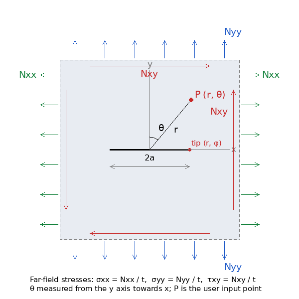
Key Assumptions
Linear elastic, infinite plate, straight through crack with traction-free faces, uniform far field. The faces must open: a compressive σy′y′ gives a negative KI and the elastic solution overlaps the faces, which is not physical (the tool flags it). Plasticity is confined to a small zone at the tips (small-scale yielding) for K to govern.
Solution
In the crack frame (x′ along the crack, y′ normal) the far field is σx′x′, σy′y′, τx′y′. Westergaard's function Z(z) = z/√(z² − a²), with the branch cut on the crack, gives
Mode I (S = σy′y′): σxx = S(Re Z − y Im Z′) + (σx′x′ − S), σyy = S(Re Z + y Im Z′), τxy = −Sy Re Z′
Mode II (T = τx′y′): σxx = T(2 Im Z + y Re Z′), σyy = −Ty Re Z′, τxy = T(Re Z − y Im Z′)
with Z′ = −a²/(z² − a²)3/2. The uniform term (σx′x′ − S) is Sih's correction for a far field that is not equal-biaxial: the stress parallel to the crack passes through undisturbed and shows up only as the T-stress T = σx′x′ − σy′y′. The field is exact and closed-form. Near a tip it reduces to the Irwin K field, σij = KI fij(φ)/√(2πr) + KII gij(φ)/√(2πr), with
KI = σy′y′√(πa), KII = τx′y′√(πa), G = (KI² + KII²)/E′, E′ = E (plane stress) or E/(1 − ν²) (plane strain).
For a uni-axial stress σ and a crack inclined by β to it, KI = σcos²β√(πa) and KII = σsinβcosβ√(πa).
Checks built into the development: the crack faces carry no normal or shear stress; the far field is recovered; ahead of the tip σyy and τxy approach K/√(2πr) (ratio 1.0001 at r = 10−4a); on the faces of a uni-axially loaded crack σxx = −σ (the classical result); the inclined decomposition above is reproduced.
Plastic Zone
With a yield strength the tool gives Irwin's first estimate of the plastic-zone size ahead of the tip, rp = (KI/Fty)²/(2π) in plane stress and /(6π) in plane strain; the elastic field, and K as a governing parameter, hold only while this is small against a and the ligament.
Reading the Plots
- The fringes are capped at three times the largest far-field component because the field is singular at the tips; the lobes ahead of the tips and the unloaded wake beside the faces are the features to look at.
- Figure 3 compares the full σy′y′ ahead of the tip with the one-term K field: they agree close to the tip and part beyond about r = 0.1a, where the far-field stress and the higher-order terms matter.
Limits
- Finite width: the secant and Feddersen corrections (Tada) multiply K; not applied.
- Crack closure, friction on the faces, kinking under mixed mode (the maximum tangential stress criterion gives the kink angle from KI, KII): not included.
- Fracture: compare KI with KIc (plane strain) or Kc; fatigue growth uses ΔK.