Tools › Structures › Beams › Section Properties › Method
Section Properties: Method
Open the Section Properties tool
Section Properties from Drawn Points
Problem Statement
Every beam calculation starts from the properties of the cross-section: the area, the position of the centroid, the second moments of area about the centroidal axes, the principal axes, the section moduli that turn a bending moment into an extreme-fibre stress, the plastic moduli that give the fully plastic moment, the first moment and width at the neutral axis that give the transverse shear stress, and the torsion constant. Handbooks tabulate them for standard rolled shapes; a machined or built-up section has to be computed. This tool computes all of them for any section that can be drawn as a closed polygon, with any number of polygonal holes.
The section is drawn on a grid: each click adds a point to the current polygon (after the selected point, so points can be inserted anywhere), points can be dragged, deleted with the right mouse button, or typed in the table beneath the drawing, and a hole is a further polygon inside the outer boundary. Curved boundaries are drawn as many-sided polygons (the circle and tube templates use 48 points, which gives the area and the second moment to 0.3 % and 0.6 %; use more points when that matters). The grid spacing input sets the snap distance and, through its unit dropdown, the unit of the drawing.
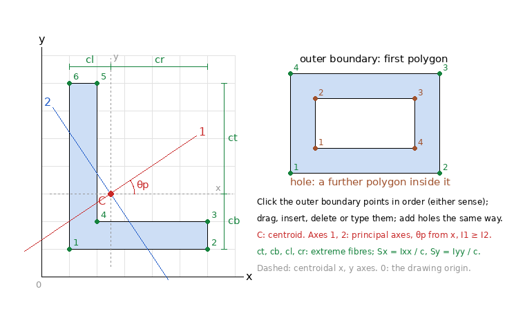
Figure A: An angle section drawn as six points, its centroid C, the centroidal axes (dashed), the principal axes 1 and 2 at θp from x, and the extreme fibre distances; a hollow rectangle is an outer polygon and a hole polygon.
Key Assumptions
Prismatic, homogeneous section; polygon boundaries; Saint-Venant torsion. The polygon formulas are exact for the polygon drawn. The torsion constant is computed numerically from Prandtl's stress function for a homogeneous bar in uniform (unrestrained) torsion; it is not the polar moment, and the warping constant and shear centre of open thin-walled sections are not computed. Composite (two-material) sections must be transformed by the analyst before drawing.
Area, Centroid and Second Moments
For a polygon with vertices (xi, yi) listed counter-clockwise, Green's theorem turns the area integrals into sums over the edges, with ai = xi yi+1 − xi+1 yi:
A = ½ Σ ai, xc = (1/6A) Σ (xi + xi+1) ai, yc = (1/6A) Σ (yi + yi+1) ai
Ixx,O = (1/12) Σ (yi² + yi yi+1 + yi+1²) ai, Iyy,O = (1/12) Σ (xi² + xi xi+1 + xi+1²) ai, Ixy,O = (1/24) Σ (xi yi+1 + 2xi yi + 2xi+1 yi+1 + xi+1 yi) ai
A hole is a polygon traversed clockwise, so its sums are negative and subtract. The second moments about the centroidal axes follow from the parallel-axis theorem, Ixx = Ixx,O − A yc², Iyy = Iyy,O − A xc², Ixy = Ixy,O − A xc yc, and the polar moment is Ip = Ixx + Iyy. The tool reports both sets so that a section drawn about a chosen origin can be combined with others by hand.
Principal Axes and Radii of Gyration
I1,2 = (Ixx + Iyy)/2 ± √[((Ixx − Iyy)/2)² + Ixy²], tan 2θp = −2Ixy / (Ixx − Iyy)
θp is measured counter-clockwise from x to the axis of the larger value I1 (the quadrant is resolved with the two-argument arctangent). Bending about a non-principal axis of an unsymmetric section produces deflection out of the plane of loading; the principal values are what the beam and column tools need, and r2 = √(I2/A) is the radius of gyration that governs flexural buckling. When every axis is principal (circles, squares, equilateral shapes) the angle is reported as zero.
Elastic Section Moduli
The extreme-fibre distances ct, cb, cl, cr are the distances from the centroid to the top, bottom, left and right of the outer boundary, and the section moduli are Sx = Ixx/c for each fibre; the governing (smaller) one gives the larger stress, σ = Mx/Sx. The principal section moduli S1 and S2 use the farthest vertex from each principal axis.
Plastic Section Moduli
In a fully plastic section the stress is the yield stress in tension on one side of the plastic neutral axis and in compression on the other; equilibrium of axial force puts that axis where it halves the area, and the plastic moment is Mp = Fy Z with Z the sum of the first moments of the two halves about the axis. The tool finds the axis by bisection, clipping the polygons with the half-plane on each side, and reports Zx, Zy, the axis positions and the shape factors Z/S (1.5 for a rectangle, about 1.12 for an I-beam about its strong axis).
Transverse Shear
The transverse shear stress at a cut parallel to the neutral axis is τ = V Q/(I t), where Q is the first moment of the area beyond the cut about the centroidal axis and t the width of the section at the cut. The tool gives Q and t at the centroidal axes, where the shear stress of most sections is largest; t is the sum of the chords of the cut inside the material, so for a hollow section it is the sum of the two wall thicknesses.
Torsion Constant
For uniform torsion of a prismatic bar the shear stresses derive from Prandtl's stress function φ, which satisfies ∇²φ = −2Gθ in the material and is constant on each boundary; the torque is T = 2 ∫ φ dA (plus 2φm Am for each hole m), so that J = T/(Gθ). The tool solves the equation by finite differences on a square grid laid over the bounding box, with the boundary fitted exactly by unequal stencil arms (Shortley–Weller). The constant on a hole boundary is not known in advance: it follows from the requirement that the warping displacement be single-valued around the hole, ∮ ∂φ/∂n ds = −2Am, which with a harmonic function per hole reduces to a small linear system. The number of cells across the larger side is an input (100 by default; the cost grows with its cube).
Checks against exact values at 100 cells: square 0.1405 a4 (exact 0.1406), rectangle 2 × 4: 7.31 (7.32), circle 1.5701 r4 (π/2 = 1.5708), tube with ri = ro/2: 1.4732 (1.4726), all with the circles drawn as 180-gons. Thin-walled and hollow sections are the harder cases; raising the cell count shows the convergence. For a circular section J = Ip; for every other shape J is smaller, markedly so for open thin-walled sections, and the polar moment must not be used in its place.
Saving and Loading Sections
A signed-in analyst can save the drawn section under a name; the points (in metres) and the computed properties (SI units) are kept on the profile and, when shared, are visible to every analyst of the entity. The saved sections appear in the "Load Section" dropdown of this tool, which restores the drawing for editing, and in the beam tools, which fill their section inputs from the saved properties in the units each input shows. A link from the My Sections page opens a section directly in this tool.
Limitations
- Curves are polygons: the circle templates are regular 48-gons by default (area 0.3 % low, second moment 0.6 % low); increase the point count for precision.
- Only simple polygons: boundaries that cross themselves, holes that touch or leave the outer boundary, and nested holes are rejected with a message.
- Warping constant, shear centre, and the stress distribution in torsion are not reported; the torsion constant is for the homogeneous bar.
- Properties are geometric: a composite section must be transformed to one material before drawing.